Introduction
Since the advent of aviation over a hundred years ago, the question of navigation quickly arose. Unlike land transport, the sky, where aircraft operate, and its weather phenomena do not necessarily allow for visual contact with the ground and physical landmarks. It became evident that flying by sight significantly limited the possibilities of finding one's way and arriving safely at the destination.
It is natural that aviation initially used what it had available, namely maritime instruments: compass, sextant, or even light beacons for night flying. However, these archaic techniques were poorly suited to its machines, which had very high speeds, and aviation needed to develop its own techniques. After the First World War, the advent of public air transport required finding solutions to ensure the transport of passengers and freight with an acceptable level of safety and precision. Here is a brief overview of the history of instrument flying to contextualise our subject.
The rapidly growing technique of wave propagation, that is to say radio electricity, which was initially used for communication, will find its application in navigation. This will enable the implementation of different types of ground beacons communicating with the aircraft's navigation instruments..
During the Interwar period, the goniometer will first appear, allowing the detection of a radio signal emitted by an antenna and guiding one towards it. This marks the birth of the radio compass. This will lead to the NDB (Non-Directional Beacon), the first true ground beacon, which is still in use today. In the same period, the first basic landing aid system appears, enabling guidance to the runway even without visual contact, known as the ILS (Instrument Landing System). Aircraft are equipped accordingly, the artificial horizon becomes widespread, and the first instrument flight training is effectively established..
The Second World War significantly accelerated the technological development of air navigation. The major innovation will be Radar, which allows a ground station to locate aircraft in flight at any time. This will foreshadow modern air traffic control, which still uses radar as a primary tool.l.
Le LORAN-C fera aussi son apparition et permet de connaitre sa position en mesurant la différence de propagation des ondes entre deux stations. Celui-ci améliora la qualité de la navigation sur les longues distances non couvertes par des NDB. Quand aucun moyen de radionavigation n’était à portée, le seul moyen était de se repérer grâce aux étoiles… L’antique sextant était installé à bord des avions de ligne long-courriers jusque dans les années 1960.
Navigation has significantly improved in accuracy with the arrival of VOR (VHF Omnidirectional Range). This ground beacon emits 360 radials. The pilot can thus know their position relative to the station at any time and join or depart from it precisely via the desired radial. These are often coupled with a DME (Distance Measuring Equipment) indicator that continuously displays the distance to the station to the nearest tenth of a nautical mile..
All these magnificent advancements have a major intrinsic drawback; they are dependent on ground-based beacons. In addition to needing to be within range, one must rely on the reliability of the installations. In short, navigation is never truly autonomous and depends on the uncertainties of the infrastructure.
The arrival of the American GPS* in the 1980s (Global Positioning System) sweeps away the issue of range with beacons as it completely frees itself from it and allows one to know their position with unparalleled accuracy worldwide. However, it remains dependent on the functioning of satellites, and for this reason, it is generally combined with other navigation sources in aviation..
The first truly independent system will be inertial navigation. Initiated for military purposes during the Second World War, it equipped airliners from the 1960s onwards. The principle is based on the detection of movement using accelerometers, which allow for the calculation of speed, heading, attitude, and thus position relative to the starting point. Once mechanical, these platforms known as INS (Inertial Navigation System) or IRS now operate using lasers and equip all airliners to this day. They have the disadvantage of being complex and therefore very expensive, and are rarely fitted to small piston aircraft, for example..
The last two navigation systems have enabled the development of the current IFR navigation technique, namely RNAV (Area Navigation).
*The generic term for satellite positioning is GNSS (Global Navigation Satellite System). Its American variant is called GPS and is still the dominant system in aviation at present. The Russians have developed their own system called GLONASS, and the European Union has developed its own, Galileo. The ICAO therefore uses the term GNSS to define this means of navigation, but we will conventionally use GPS here as it is more familiar to all of us..
What is RNAV?
Principle
Let us now look at what interests us more closely, namely RNAV. As we saw earlier, instrument flight was previously based on ground stations, commonly referred to as conventional means. RNAV allows navigation to any point without using ground beacons. These points, whether virtual or corresponding to actual beacons, are waypoints. Officially established in 1998, here is the official definition of RNAV provided by ICAO (International Civil Aviation Organization).:
“RNAV stands for Area Navigation RNAV: Capability to fly any desired flight path, defined by waypoints such as geographic fixes (LAT/LONG) and not necessarily by ground navaids”.
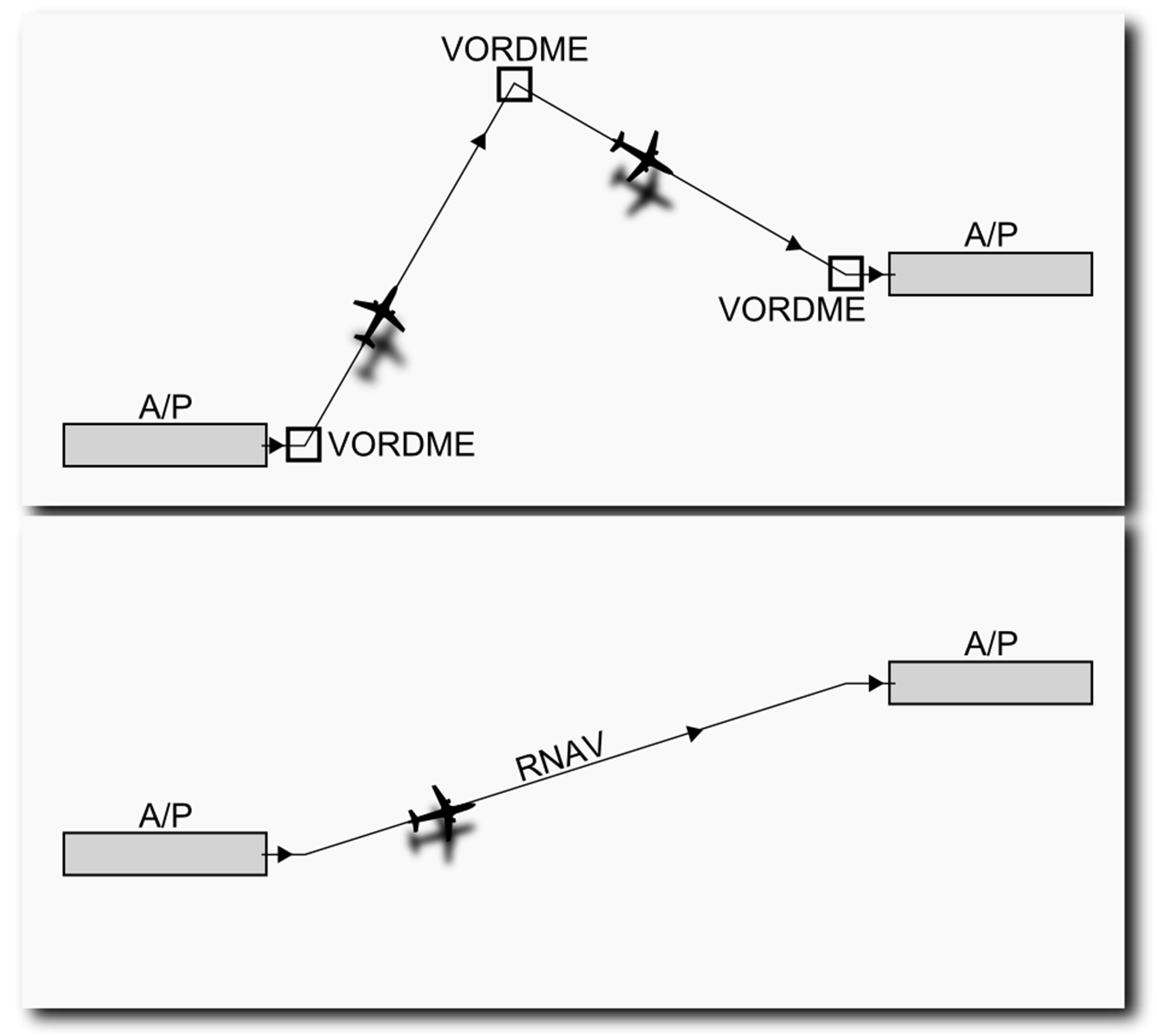
Source: https://commons.wikimedia.org/wiki/File:VORDME_vs_RNAV_model.PNG?uselang=fr#filelinks
The benefits of this system are numerous:
- Reduced costs (fewer infrastructures to maintain, move or install).
- Flexibility in adapting procedures (to change a published trajectory or waypoints).
- Precision of the position facilitating traffic regulation.
- Operational savings and time gains by flying more direct routes.
Instrument approaches that were once unachievable with conventional means (for example, at an airport surrounded by terrain).
Equipment
The arrival of GPS and inertial navigation has gone hand in hand with a modernisation of aircraft navigation systems.
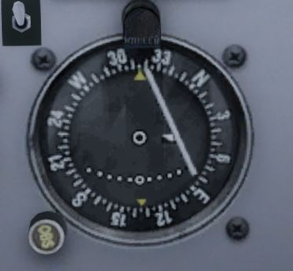
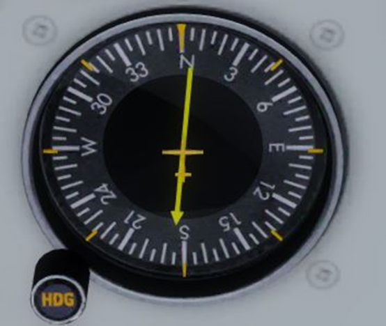
DIn the cockpits, the traditional heading indicators, HSI (Horizontal Situation Indicator), ADF (Automatic Direction Finder) or CDI (Course Deviation Indicator) have now disappeared from commercial aircraft, or are used strictly as backup or secondary instruments (although they still exist in smaller aircraft even equipped for IFR). You have certainly seen them before and they looked like this. :
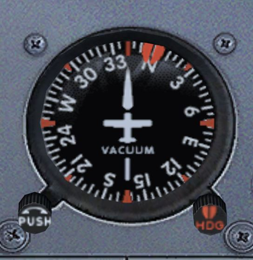
Heading indicator
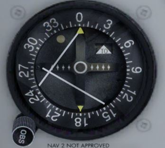
CDI with ILS
Basic CDI
ADF
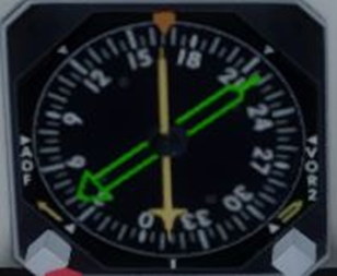
RMI
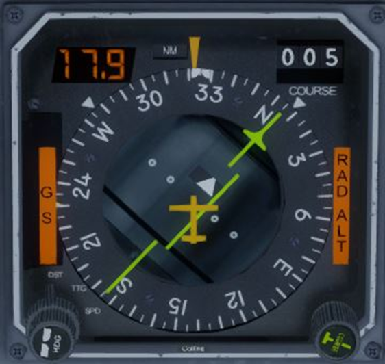
HSI
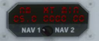
DME
To navigate using RNAV, aircraft require suitable modern equipment. They can be divided into two categories..
- The "small" aircraft, let us consider what ranges from the small single-engine to the twin-engine piston single pilot. They generally rely on a GPS that determines its position using the GPS antenna. The waypoints of the flight plan are entered into it. The pilot has an interface displaying, among other things, a map with the real-time position of the aircraft. Therefore, there is only one RNAV navigation source, the GPS (the installation of 2 GPS units is possible to increase redundancy)..
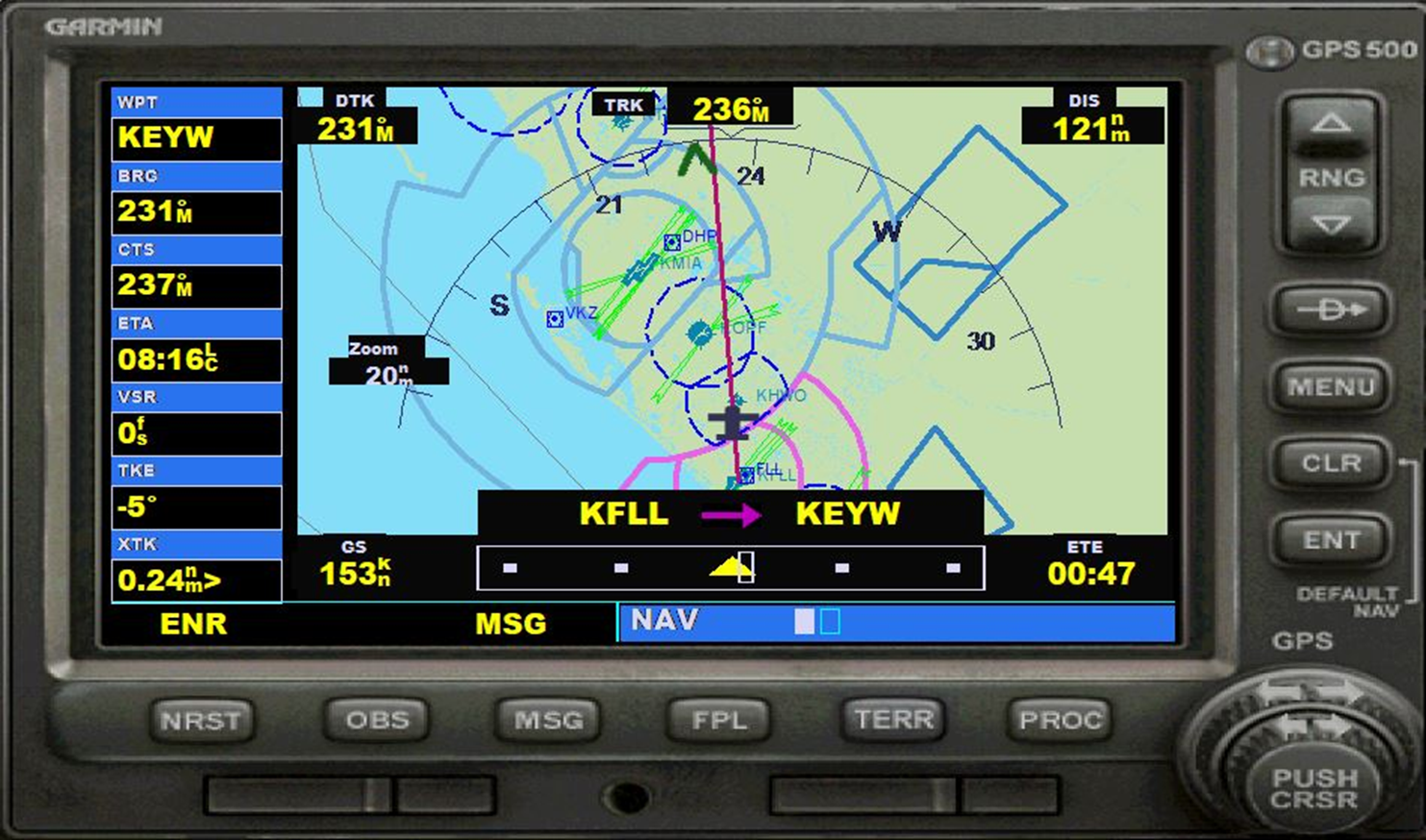
GPS Garmin 500, a very common model in general aviation
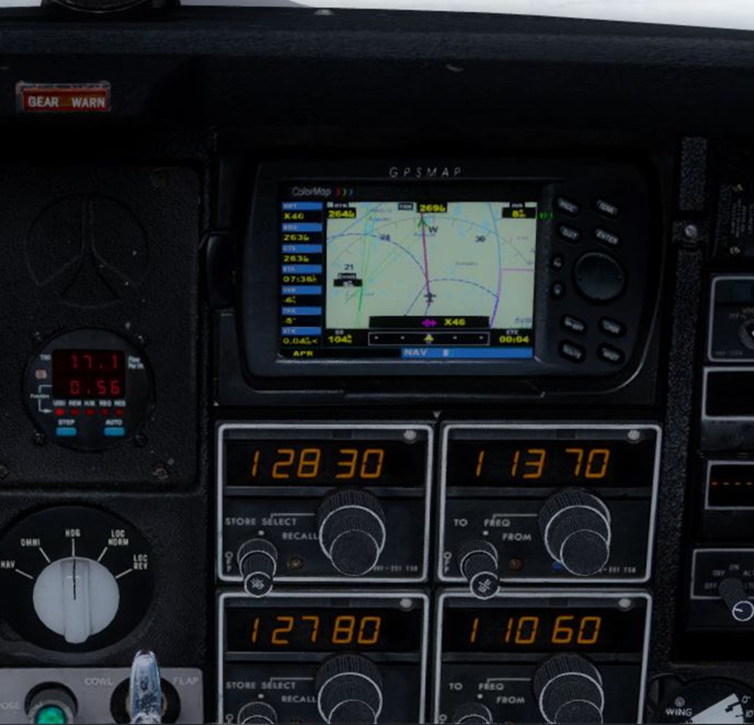
Iclassic integration of GPS into the dashboard
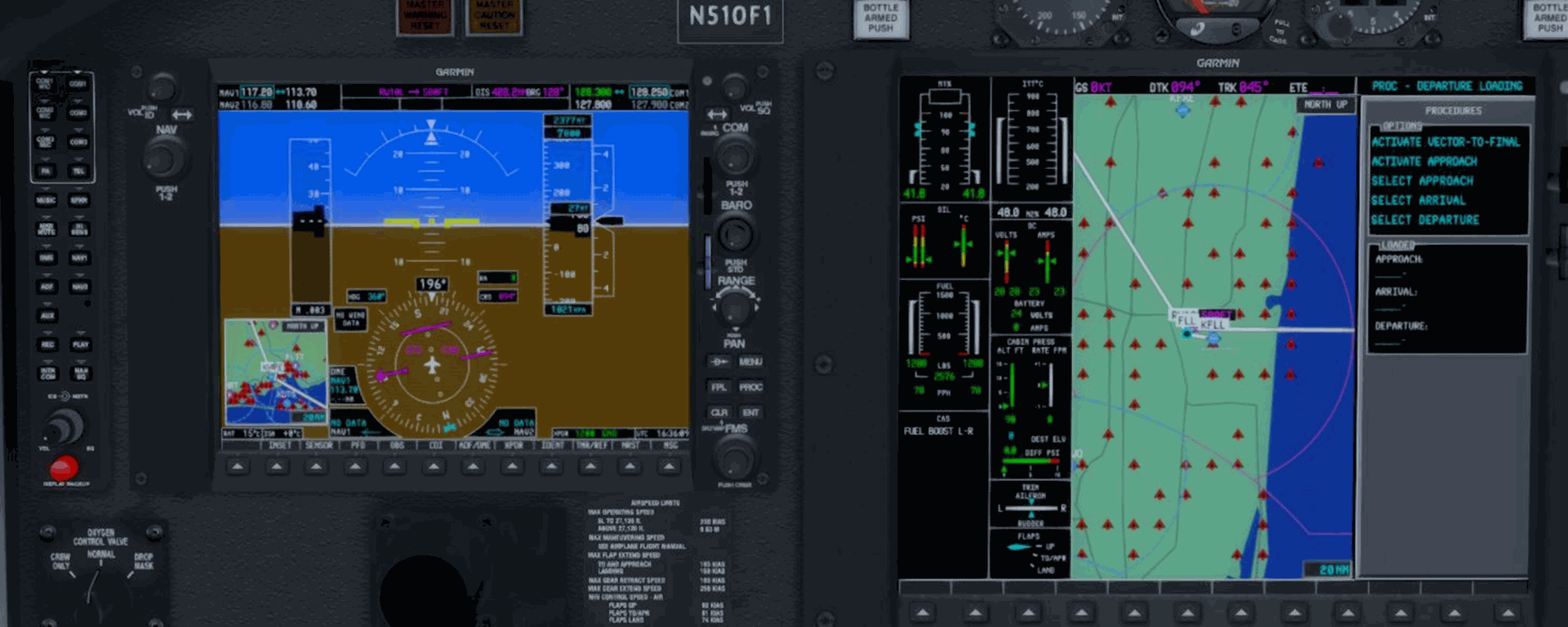
Garmin 1000: GPS integrated into a "Glass Cockpit" avionics system, here on a Cessna Citation Mustang
- On "large" aircraft, ranging from small business jets to large airliners, the navigation system is more advanced and, in addition to navigation, it allows for overall management of the aircraft's performance, such as fuel consumption, altitude, and speed: this is the famous FMS (Flight Management System). Like a GPS, it displays navigation information on a map, replacing the conventional instruments we mentioned earlier. It is worth noting that the first aircraft equipped with inertial navigation systems, such as the early Boeing 747s, still retained conventional instrumentation and did not have an FMS, and therefore could not yet be considered RNAV..
Here are some illustrated examples :
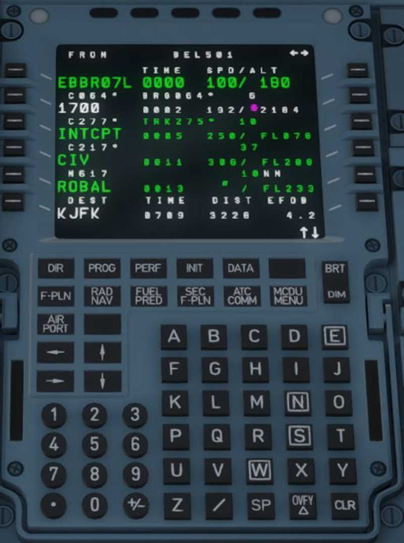
MCDU Airbus A330. Here on the F-PLAN page which lists the programmed waypoints
ND on Airbus A330
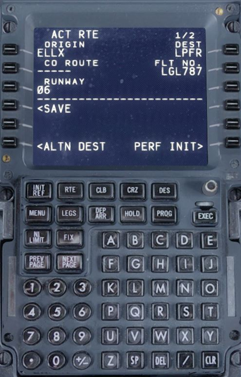
CDU on Boeing 737NG
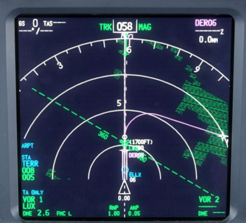
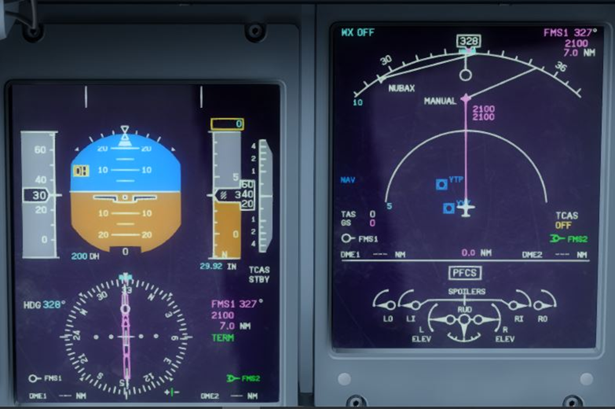
EHSI on Boeing 737NG
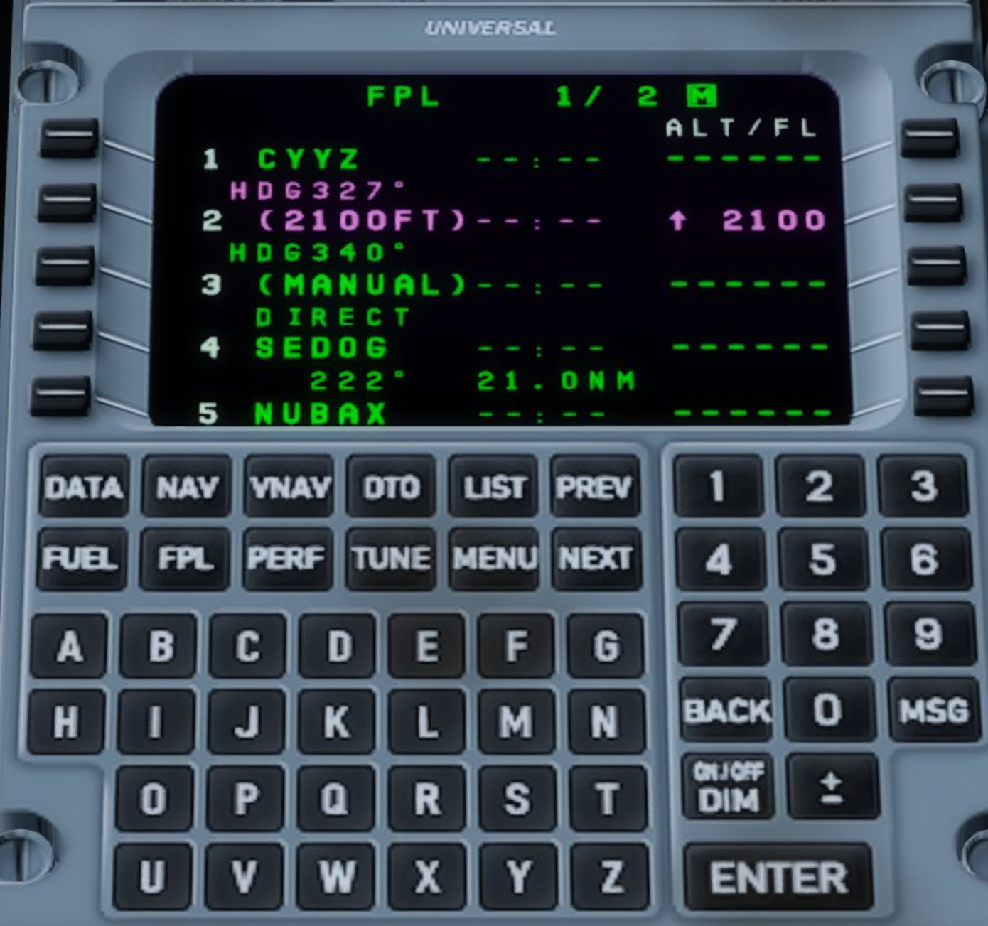
FMS Universal on Bombardier Q400
PFD and MFD on Q400
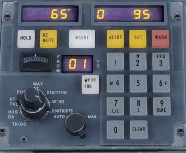
Delco Carroussel on a Lockheed L-1011 Tristar. The interface of the first inertial navigation systems (INS) and the ancestor of the FMS. You could enter the coordinates of 10 waypoints..
The other advantage of the FMS is that it can use several different position sources and can make use of various sensors.:
GPS
VOR/DME
DME/DME
INS
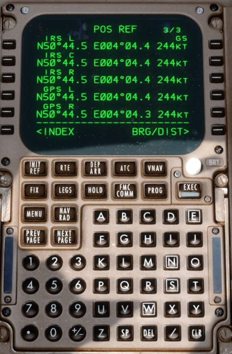
The FMS Boeing 747-400 sources its data from 3 IRS and 2 GPS here
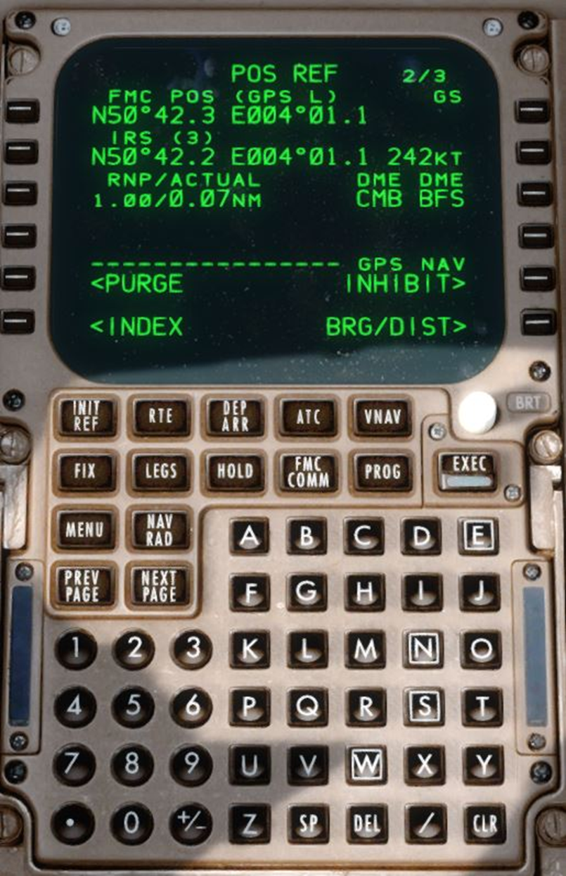
...but also of 2 DME
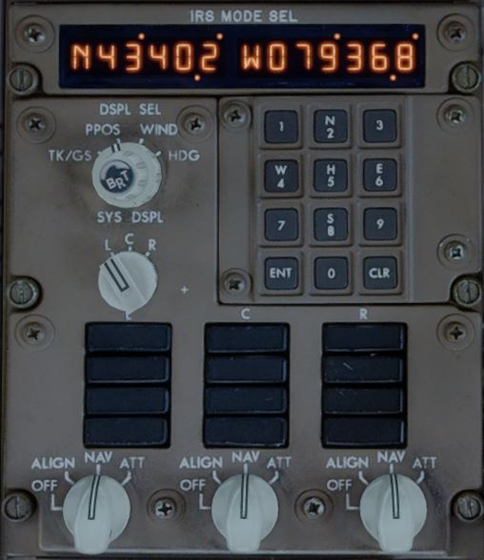
Inertial Reference System (IRS) controls on a Boeing 757. There are three of them here. These significantly enhance the system's performance, which is based on criteria that we will discuss later.
Since it has become the norm, your companion that will carry out the navigation for the majority of the flight will be the autopilot. IFR-certified aircraft are now required to have autopilot that can at least maintain altitude and heading, and mostly follow a desired trajectory from navigation systems. Two modes are distinguished:
- On the horizontal plane: generally referred to as NAV or LNAV (Lateral Navigation). It simply involves following the waypoints entered in the route.
- In terms of vertical navigation: the most advanced among them are equipped with it and is conventionally referred to as VNAV (Vertical Navigation) or less commonly PROF (Profile). It automatically ensures compliance with the altitude constraints entered in the route to a given waypoint (during a STAR arrival procedure or an RNAV approach, for example), taking into account the aircraft's performance..
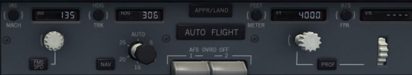
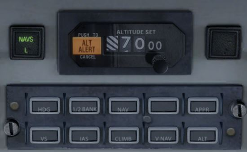
There are different philosophies depending on the manufacturers :
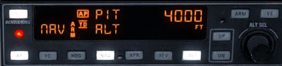
Bendix/King interface current in general aviation. Here on a Beechcraft Bonanza. The NAV mode follows horizontal navigation and there is no VNAV.
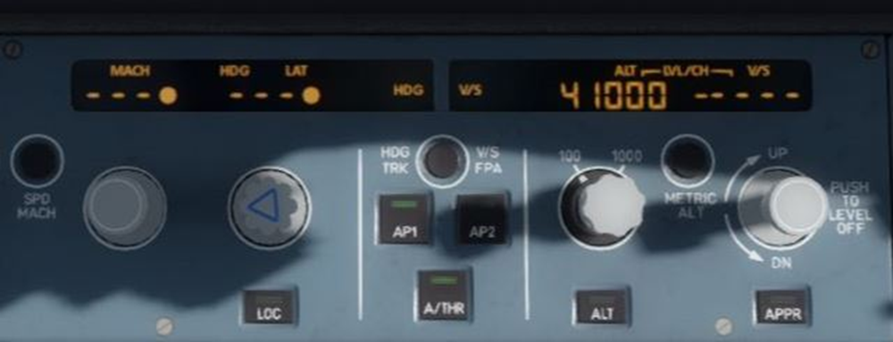
On an Airbus, when the "managed" mode is selected, the value is replaced by the 3 dashes and the dot indicates that the FMGS controls the navigation.
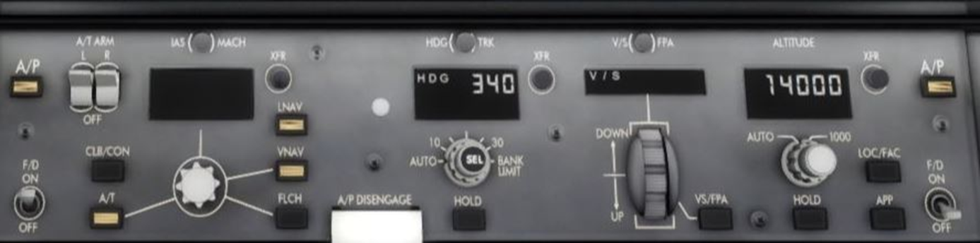
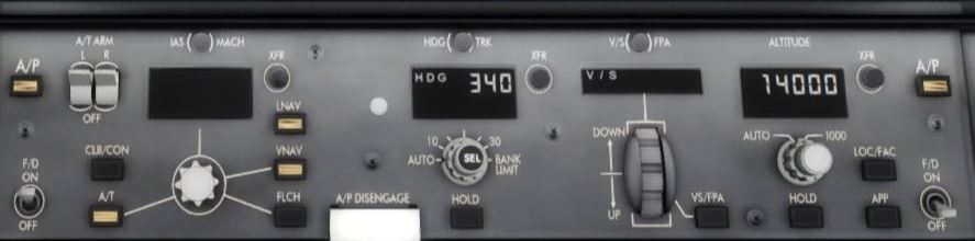
On a Boeing, the famous LNAV/VNAV is still the foundation of flight management. Here on a 787.
On the original McDonnell Douglas autopilot of the Boeing 717, the VNAV is called "PROF".

The CRJs are not necessarily equipped with VNAV. The pilot must intervene by adjusting the rate of descent.
The Saab 340 has a VNAV mode only for descent.
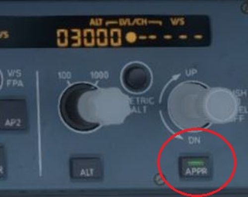
Some autopilots, like here on an Airbus A330, are capable of following an RNAV approach by simply engaging the "approach" mode as one would with a traditional ILS..
Introduction to PBN
We could not go any further in our presentation without mentioning the concept of PBN (Performance-based Navigation).
To operate in RNAV, navigation must meet defined criteria for performance, equipment, infrastructure, and appropriate crew training according to the corresponding procedure. The evolution of aircraft systems made it possible to implement an increasing number of RNAV procedures. However, each state or manufacturer had a fairly liberal interpretation of the operational aspects recommended by the ICAO.
To standardise the standards and more rigorously define the performance criteria required in airspace, this institution decided to introduce PBN in 2004. It is officially defined in ICAO document 9613. :
« The PBN concept specifies that aircraft RNAV system performance requirements be defined in terms of accuracy, integrity, availability, continuity, and functionality, which are needed for the proposed operations in the context of a particular airspace concept.. »
LThe PBN is therefore responsible for establishing specified performance categories that are classified into two main categories :
- RNAV X*: Defines the performance of navigation but the aircraft does not have alerting and monitoring functions for it.ci.
- RNP X* (Required Navigation Performance): Requires additional alerting and monitoring functions on board.
*“X” corresponds to the minimum navigation accuracy in nautical miles (nm) laterally required for 95% of the time.
These specifications are required depending on the phase of the projectl :

The performance of navigation systems is evaluated by 3 criteria :
- Position accuracy : difference between the actual position and the displayed positione
- Integrity : The reliability of the displayed informatione
- Continuity : The absence of interruption
Logically, the more critical the flight phase is and the higher the degree of precision and reliability required for it to be executed safely, the more efficient the system will need to be. For example, a final approach to an airport in a mountainous area will require more precise navigation than flying over an ocean at cruising altitude..
Approach procedures (RNP APCH)
In terms of navigation, the most delicate phase of flight is essentially the final approach. This requires getting closer to the ground and therefore to potential obstacles, and guiding the aircraft to that small stretch of tarmac known as the runway. These approaches do not rely on ground navigation aids (ILS, VOR, ADF) and instead trust more recent equipment (GPS, INS) whose operational reliability is subject to particular monitoring. Consequently, they are subject to a specific classification..
The first RNP approaches (commonly referred to as "RNAV approaches") were implemented at airports where no conventional approach means were available. In recent years, the trend has been towards their generalisation as a substitute, even to the detriment of ILS or VOR or NDB approaches..
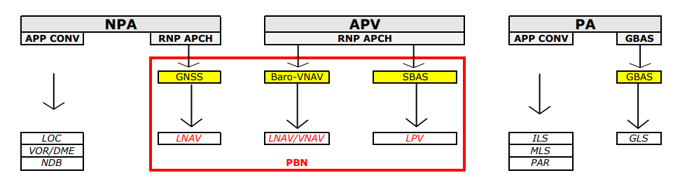
The RNP approaches are divided into two categories :
- Non-precision approaches (NPA), WITHOUT vertical guidance
- Vertical guidance approaches (APV), which the ICAO does not consider as precision approaches (PA).
The two categories are themselves part of a broader categorisation that includes all approaches, including conventional ones..
Here are the different scenarios you may encounter on your approach charts :
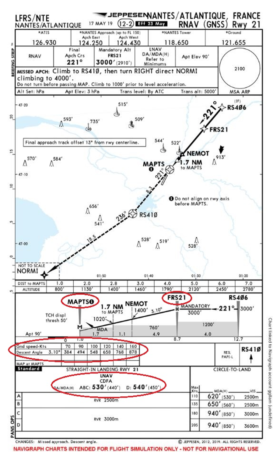
LNAV (NPA)
Like other non-precision approaches (VOR, NDB, LOC), it is best flown using the CFDA (Continuous Descent Final Approaches) technique. Therefore, there is no vertical guidance. Horizontal guidance is provided by following the path of the waypoints on the map (Nav Display). There is also a horizontal deviation indicator similar to that of a Localizer.
Consequently, this approach is inherently relatively imprecise and imposes quite high minimums.
In our example, once at the Final Approach Fix "FR21" at 3000 ft, it is necessary to adopt a descent rate that allows for a fixed angle of 3.10° down to the minima of 530 ft or 540 ft as applicable. The runway should be in sight no later than passing the point "MAPTS", after which we proceed towards runway 21; otherwise, we go around and follow the published missed approach procedure. It is worth noting that the latter also works in RNAV..
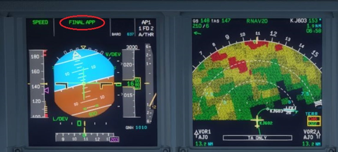
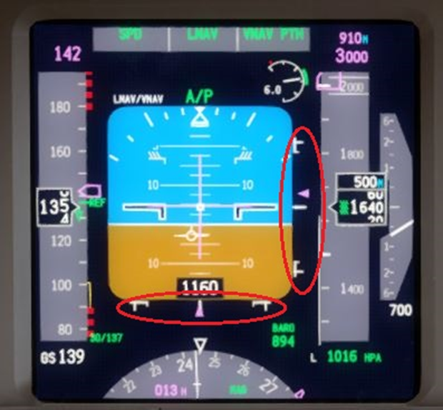
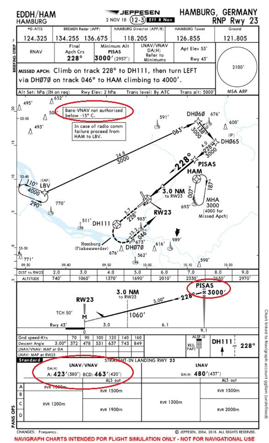
LNAV / VNAV (APV)
In this scenario, we gain vertical guidance. The navigation system will display in front of the pilot's eyes the vertical trajectory to follow in the form of a glide path very similar to, if not identical to, that of an ILS; this is the vertical deviation indicator. To calculate this trajectory, the system uses BARO-VNAV, which takes the altitude detected by the aircraft's altimeter as its source..
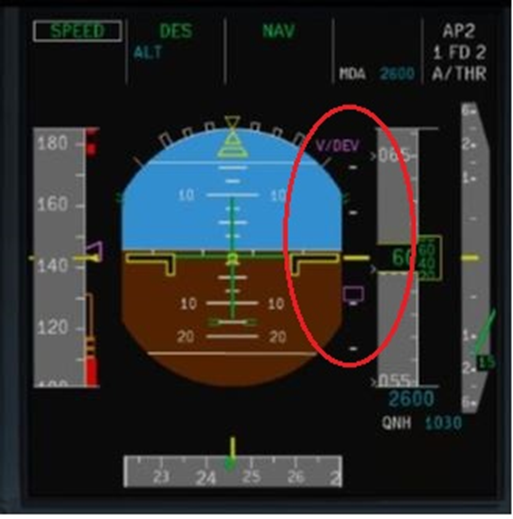
Ivertical deviation indicator on an Airbus A320
On the Boeing 777, it is complemented by a horizontal deviation indicator.
The downside is that this procedure is subject to altimetric errors (incorrect calibration, temperature effects, instrument errors). More precise than an LNAV approach, it does not allow descent as low without visibility as a true precision approach.
Upon arriving at the FAF "PISAS" at 3000 ft, the pilot follows the vertical deviation indicator on his instrument as he would with the Glide Path of an ILS. He must be aware that the accuracy of this trajectory depends on the proper functioning of the altimeter. It should be noted that below an ambient temperature of -15°, it is indicated that this approach is not permitted. Indeed, the altitude reading error would be too significant to conduct it with acceptable vertical precision..
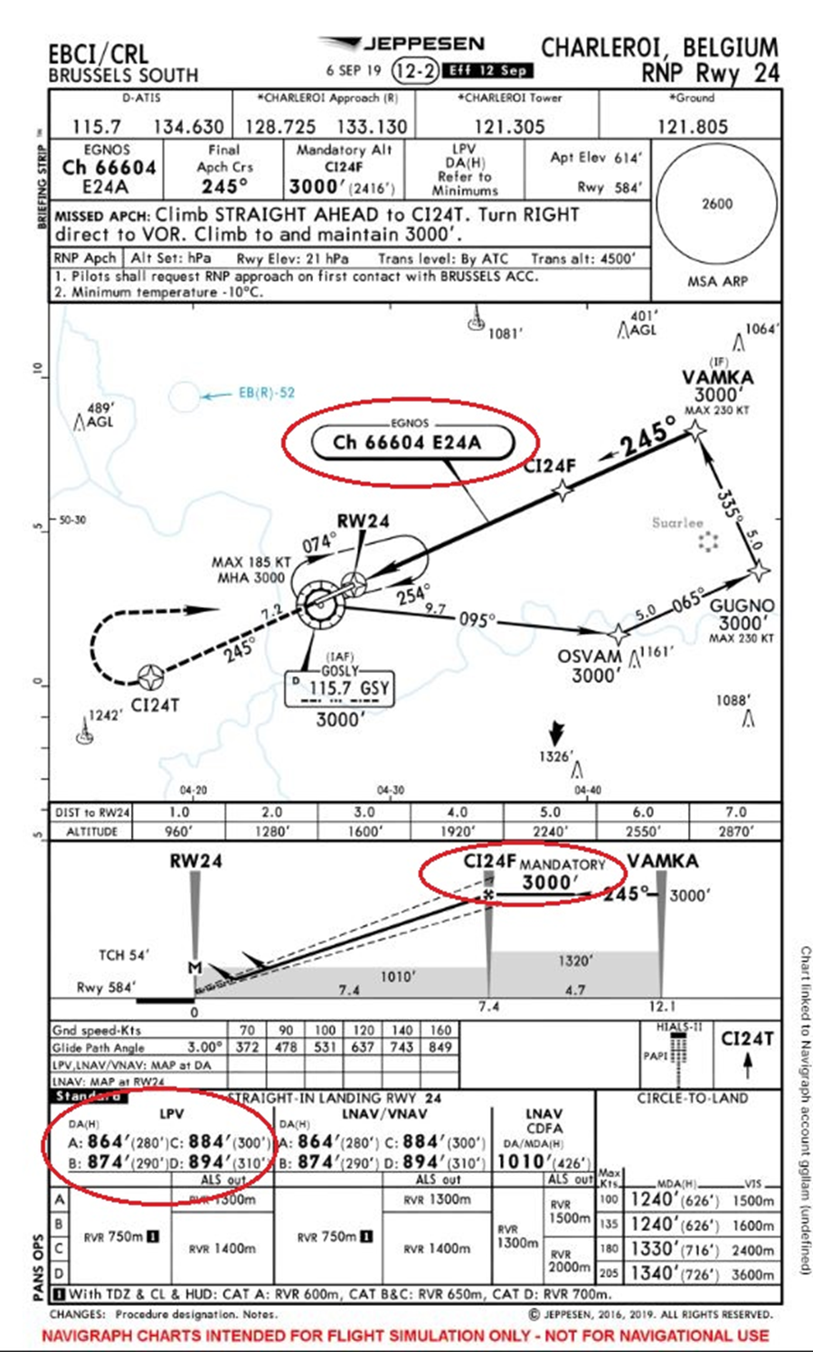
LPV (APV)
LPV stands for Localiser (Performance with Vertical Guidance). To solve the inherent problem of altitude error, it was necessary to have vertical guidance without relying on an altimeter. In the absence of an external reference such as the Glide Slope, the solution was to adopt the principle by using satellites.s.
The GPS receiver determines its position using a constellation of 24 satellites orbiting the Earth and detectable worldwide. To implement LPV approaches, it is supplemented in certain regions of the globe by geostationary satellites. This will allow for achieving a precision and redundancy that enables reliance solely on GPS for vertical guidance. It is a virtual Glide Slope created by the GPS that the pilot follows on their instrument as they would for an ILS approach..
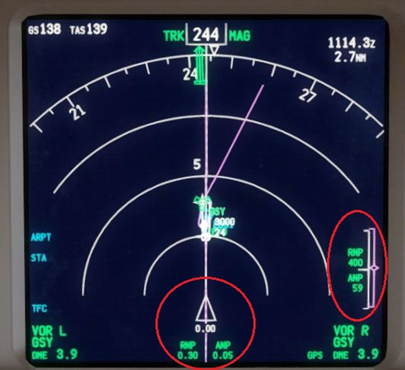
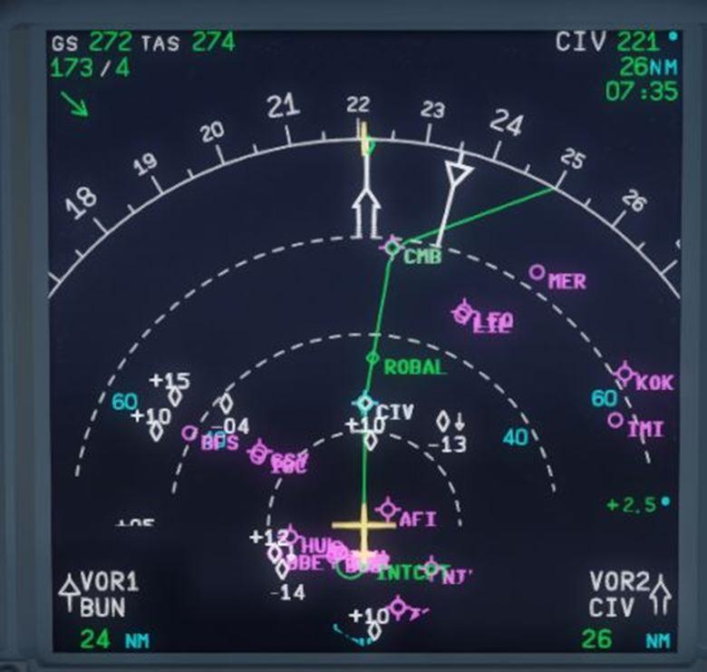
On the Boeing 777, the EHSI also displays horizontal and vertical deviations. Here, we are perfectly aligned with the approach and a tad too low on the glide path. In green, the required navigation performance (ANP) and the current system performance (RNP). Therefore, we are well within the tolerances to continue this LPV approach..
It is the SBAS system (Satellite-based Augmentation Systems). Here is the list and the variations of the regions of the world covered :
- North America : WAAS
- Europe : EGNOS
- Russia and CIS : SDCM
- India : GAGAN
- Japan : MSAS
Its operation is then quite different from that of an LNAV/VNAV approach, but the altitude issues are eliminated and this type of approach allows for minima that are almost identical to those of an ILS..
Passing "CI24F", we descend to the minima following the displayed final approach path. It should be noted that the ILS frequency has been replaced by an EGNOS frequency. This corresponds to the procedure in question, but the system automatically programmes it when the pilot selects the approach..
RNAV APCH AR (Authorization Required)
This is both the most demanding and the most innovative approach of all RNAV approaches. Some airports are located in mountainous areas, and the approaches to access them are dotted with terrain, meaning potentially deadly obstacles. The approaches, both conventional and RNAV, that we have seen previously consist of straight trajectories guiding the aircraft to the runway. What do you do when a mountain is a few kilometres in front of the runway, preventing the establishment of an approach that provides an acceptable approach plan? ?
By freeing itself from conventional means that require following straight trajectories, RNAV opens up a very interesting perspective. Why not create curved trajectories that would avoid obstacles? Thus, airports with difficult operational access that could only rely on non-precision approaches with less advantageous minima, ending with quite delicate visual manoeuvres, have implemented this new type of approach. As a result, these runways become accessible with instrument approaches at more suitable minima.s.
These approaches remain quite delicate to execute, and the reliability of navigation is even more crucial. Authorisation from the aviation authorities of the relevant country is mandatory. Indeed, operators are required to provide their crews with adequate training and to train them to operate on this particular type of approach. The procedure is similar to other GPS-based RNAV approaches, but the aircraft must be equipped with at least one INS platform and two DME receivers in order to be approved. Some procedures can thus offer remarkably high levels of precision..
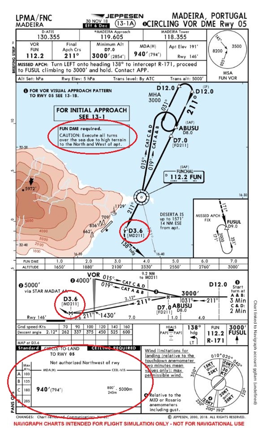
The airport of Madeira is an excellent example illustrating the benefits of RNAV APCH AR approaches. Let’s compare these two cases. :
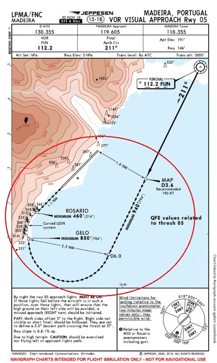
The runway 05/23 is built on a mountainside platform, making any normal IFR approach to runway 05 impossible. Here is the VOR DME procedure which requires descending to 3.6 nm beyond the Funchal VOR (FUN) down to minima of 940 ft. If the runway is in sight, a spectacular visual manoeuvre must then be executed by turning right to face the runway at only 1.1 nm from it… Additionally, a minimum visibility of 5000 metres and a ceiling of 800 ft are required to commence this approach (!).
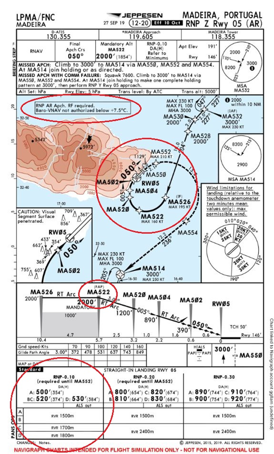
The implementation of the RNP Z (AR) procedure on this same runway has remarkably lowered the minima, as they are now only 530 ft in altitude and 1800 m (CAT D) in visibility for an RNP accuracy of 0.1. Once at the FAP "MA522" at 2000 ft, it is "sufficient" to engage the VNAV mode and follow the indicated waypoints until the minima just before the point "MA502". Despite the hostile environment, it is possible to descend relatively close to the runway and align with it without any visibility, which is impossible with a conventional approach in this case. However, it should be noted that this approach is not permitted below an outside temperature of 7.5°C. Indeed, RNAV APCH AR approaches operate on the principle of BARO-VNAV..
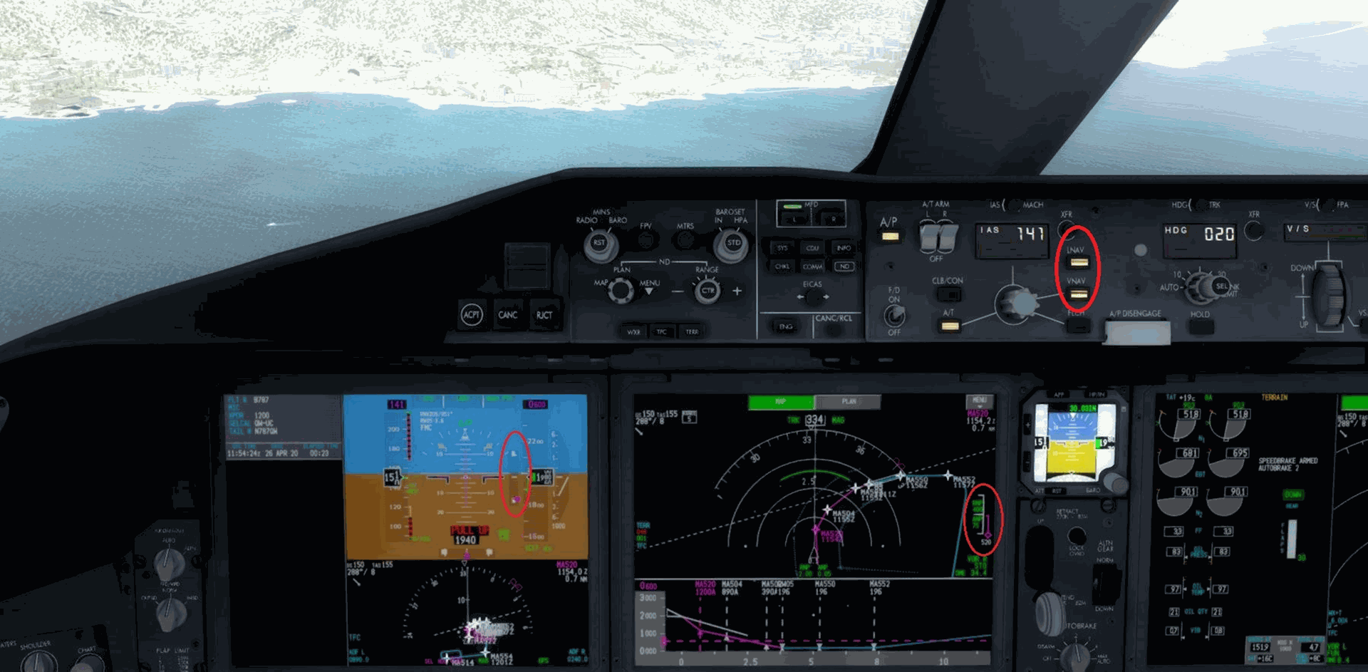
DDemonstration of this approach with the Boeing 787. We are perfectly following the horizontal trajectory but are, however, 520 ft too high. The autopilot is engaged and is following the approach previously entered into the FMC in LNAV and VNAV mode..
References
To delve into this topic, here is some reading from official sources regarding RNAV and its applications :
- Doc 9613 of the ICAO governing the PBN.
- RNAV approaches detailed in this training from the French DGAC.
- RNP APCH AR approaches according to ICAO, with a short lesson to deepen.
- SBAS explained by EASA, the European agency.