Introduction
The instrument flight or IFR (Instrument Flight Rules) is not limited to the use of instruments for navigation when visibility becomes insufficient for visual flight. This flight regime is a vast set of rules and procedures precisely defined by regulations. With the exception of private flying in light aircraft, the vast majority of commercial air transport operates under IFR. Consequently, Flight Simulator and flight simulation in general generate a strong interest in instrument flying. Whether the user flies online or offline, with or without air traffic control, in good or bad weather, the availability of increasingly realistic aircraft for our simulators makes the knowledge of instrument flying essential to master and exploit the full potential of flight and the remarkable possibilities offered by software developers. Although it may be tempting to jump straight into IFR at the controls of a favourite airliner, or at least any complex aircraft, it will never be easy to gain a good mastery without having acquired the basics of the science of instrument flying. The objective of this module is to acquire the fundamentals of instrument flying and will be limited to a certain framework. This means that we will consider this training in the conditions of a student who is obtaining their basic qualification, namely on a single-engine aircraft using conventional radio navigation means. This manual establishes the essential theoretical foundations to be assimilated with an approach that is both precise yet simple and educational so that the material is accessible to all. We will not delve into overly technical considerations that could divert us from our primary recreational objective. Before starting this course, it is necessary to specify that we will use the standards defined by ICAO, that is to say, at a global level to refer to the regulations regarding instrument procedures. However, we should be aware that nuances may exist between different aviation authorities, such as between EASA (Europe) and FAA (United States) in particular.
Table of contents
1 Basic principles
.....1.1 Definitions
..........1.1.1 Aerodynamics
..........1.1.2 Attitude
..........1.1.3 Altitude
..........1.1.4 Direction
..........1.1.5 Speed
..........1.1.6 In summary: the triangle of speeds
.....1.2. Primary Instruments
..........1.2.1 Artificial horizon (AI)
..........1.2.2 Altimeter
..........1.2.3 Vertical speed indicator (VSI)
..........1.2.4 Speed indicator(ASI)
..........1.2.5 Turn and Slip
..........1.2.6 Magnetic compass
..........1.2.7 Directional Gyro (DG)
..........1.2.8 Gyromagnetic Compass (HSI)
.....1.3.Instrument flying
..........1.3.1 Selective Radial Scan
..........1.3.2 Straight and level flight
..........1.3.3 Turn
..........1.3.4 Climb and Descent at constant speed
..........1.3.5 Climb and Descent at constant rate
..........1.3.6 Vertical navigation
..........1.3.7 Drift Correction
..........1.3.8 Effect of the wind on speed
2. Radio Navigation Aids
.....2.1 ADF/NDB
..........2.1.1 Principle
..........2.1.2 Instrument
.....2.2 VOR
..........2.2.1 Principe
..........2.2.2 Instrument
.....2.3 DME
..........2.3.1 Principe
..........2.3.2 Instrument
.....2.4 ILS.
..........2.4.1 Principe
3.Navigation
.....3.1 VOR Navigation
..........3.1.1 Position
..........3.1.2 QDM/QDR
..........3.1.3 Radial interception
..........3.1.4 Passage overhead
..........3.1.5 Wind effect
.....3.2 ADF Navigation
..........3.2.1 Position
..........3.2.2 Interception
..........3.2.3 Wind effect
4. Procedures
.....4.1 Circuit d'attente - Holding Pattern
.....4.Reversal Procedure
.....4.3 DME Arc
5. Approaches
.....5.1 Segments
.....5.2 Classification
.....5.3 Minimums & Categories
.....5.4 Typeq d'Approches
..........5.4.3 Visual approach / Circle to land
1. Basic principles
1.1 Definitions
1.1.1 Aerodynamics
Before we delve into a course on flight mechanics, here is a brief reminder of the fundamental concepts of the aerodynamic forces acting on the aircraft:
Weight (W) : Force exerted by Earth's gravity on the aircraft
Lift (L) : Vertical lift force generated by the movement of the aircraft and perpendicular to it.
Trust (T) : Horizontal forward force produced by the engine.
Drag (D) : Horizontal force opposing the thrust and created by air resistance.
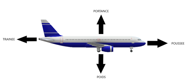
Lift opposes weight, thrust opposes drag.
Load factor (n) : Ratio between the actual weight and the apparent weight of the aircraft. In stabilised horizontal flight, it is 1 (1G):
- In a turn, it increases with the bank angle because the centrifugal force adds to the weight of the aircraft.
- In straight horizontal flight, it varies in the case of a rapid change in trajectory on the vertical plane.
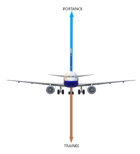
In straight and level flight, lift balances weight.
IMAGE
In a turn, the load factor created by the centrifugal force makes the aircraft feel heavier than it actually is: this is the apparent weight. To prevent the aircraft from descending and to maintain altitude, it is necessary to compensate by increasing lift.
1.1.2 Attitude
Pitch Attitude (ATT) : Angle between the longitudinal axis of the aircraft and the horizontal.
Flight Path Angle/Slope (FPA) : Angle between the flight path of the aircraft and the horizontal.
Angle of Attack* (AOA) : Angle between the longitudinal axis of the aircraft and the trajectory.
Relative Airflow : Airflow parallel to the aircraft's trajectory.
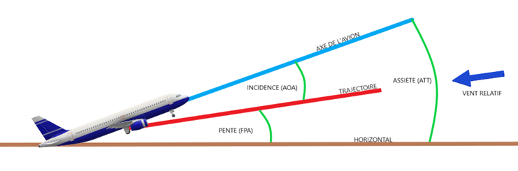
- The pitch (ATT) is displayed on the artificial horizon.
- The flight path angle (FPA) allows for following the desired approach or climb trajectory.
- The angle of attack (AOA) informs us about aerodynamic performance, particularly stall.
*There is, strictly speaking, a distinction between the angle of incidence and the angle of attack, but for the sake of simplicity, we will associate them in this course..
1.1.3 Altitude
International Standard Atmosphere (ISA) : By convention, when the atmospheric conditions at sea level are :
Outside air temperature (OAT) : 15°C
Pressure : 1013.25 hPa
Altitude (AMSL) – Altitude Above Mean Sea Level : Height above mean sea level :
Indicated: read on the altimeter
True: corrected for the variation in density
Height (AGL) – Altitude Above Ground Level : Height relative to the ground
Flight Level (FL) : Altitude relative to the reference of 1013.25 hPa
QNH: Atmospheric pressure measured at mean sea level
QFE: Atmospheric pressure measured at an airfield
Altitude Transition altitude (TA) : During the ascent, the altitude above which height is expressed in Flight Level (FL).
Transition Level (TL): During descent, the flight level below which altitude is expressed in Altitude (AMSL).
Vertical Speed (V/S) : Taux de descente ou de montée exprimé généralement en pied par minute (Ft/mn).
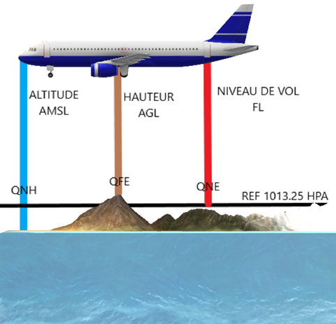
- When one adjusts the altimeter barometer :
- the QNH, we obtain the altitude
- lthe QFE, the height above the groundn
- the QNE, the level of vol
1.1.4 Direction
Heading (HDG) : Direction expressed in degrees where the axis of the aircraft points
Route (TRK) : Direction of the aircraft expressed in degrees relative to the ground
Cross Wind (X-Wind) : Perpendicular component of the wind relative to the aircraft's axis expressed in speed units (usually in knots))
Wind Correction Angle (WCA) : Angle between the Heading required (HDG) to compensate for the effect of crosswind and the desired Track (TRK)
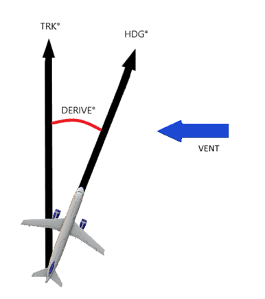
To maintain a constant track, one must head into the wind to compensate for the crosswind.
The drift correction to be applied depends on both the lateral component of the wind and the true airspeed of the aircraft.
Magnetic declination (D) : Angle between the direction of magnetic North and geographic North
Deviation (d) : Angle between the direction of magnetic North and compass North
Variation (W) : Angle between the compass North direction and true North
True Heading/Route (Cv/Rv) : Heading/Route relative to true North
Magnetic Heading/Route (Cm/Rm) : Heading/Route relative to Magnetic North
Cap/Compass route (Cc/Rc) : Heading/Route relative to the compass North
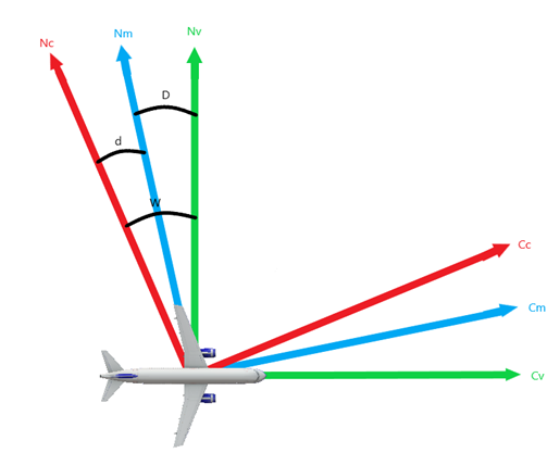
In the diagram above, it concerns the heading, but the principle also applies to the course.
1.1.5 Speed
Indicated Airspeed (IAS) : Speed measured by the Pitot tube and displayed on the anemometer
Calibrated Airspeed (CAS) : Corrected indicated airspeed for instrument errors
True Airspeed (TAS) : Calculated speed of displacement in the air mass and corrected for air density
Ground Speed (GS) : Ground speed and corrected for effective wind (headwind or tailwind
Tailwind/Headwind (TL/HD) : Component of the wind parallel to the aircraft's movement
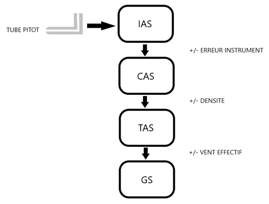
The IAS is measured by the instrument. The CAS, TAS, and GS are derived from it by calculation.
Mach Number (M.XX) : Ratio between true speed and speed of sound
1.1.6 In summary: the triangle of speeds
The triangle of velocities encapsulates the effect of the wind on the direction and speed of the aircraft in flight and allows for a visual representation of the situation.
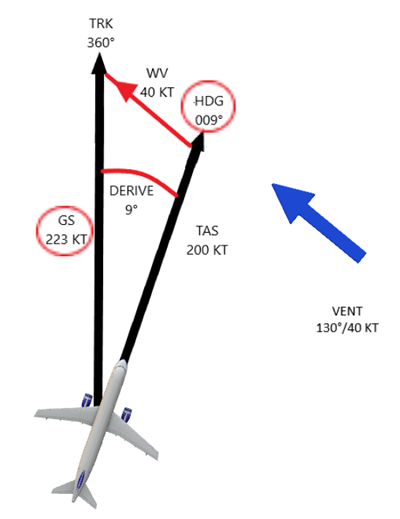
Let's break down the situation with the example above:
We must follow a track (TRK) of 360° and our true airspeed (TAS) is 200 knots. We have a wind coming from a direction of 130° at a speed of 40 knots. It is noted that the wind is coming from our rear right.
What heading should we follow to take this route?
We must therefore determine the wind correction angle (WCA). To do this, we can use the excellent calculation tool E6BX which allows for the saving of tedious calculationss.
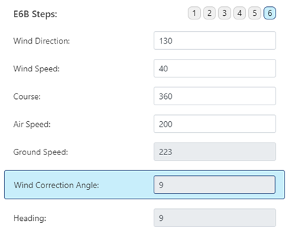
- The drift correction to be applied is 9° to the wind, therefore: 360° + 9° = 9°. Thus, a heading (HDG) of 009° should be followed..
- The tailwind component brings our ground speed (GS) to 223 knots.
In conclusion, the stronger the crosswind, the greater the necessary drift correction angle will be in order to maintain our course.
1.2 Primary Instruments
1.2.1 Artificial horizon(AI)
The artificial horizon is the main instrument for instrument flight. Without external visibility, the pilot uses it to know the attitude and bank angle of the aircraft..
It consists of a model representing the position of the aircraft in relation to the horizon on two graduated axes (vertical for the attitude, horizontal for the bank).
For light aircraft, the measurement is generally provided by a 2-degree-of-freedom gyroscope. Modern aircraft tend to be equipped with more sophisticated electromechanical systems of the AHRS (Attitude and Heading Reference System) type, as is the case with the Garmin 1000 avionics, for example.
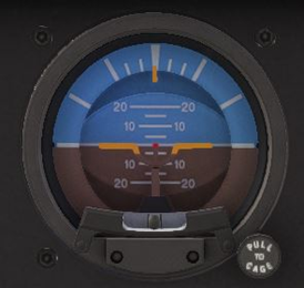
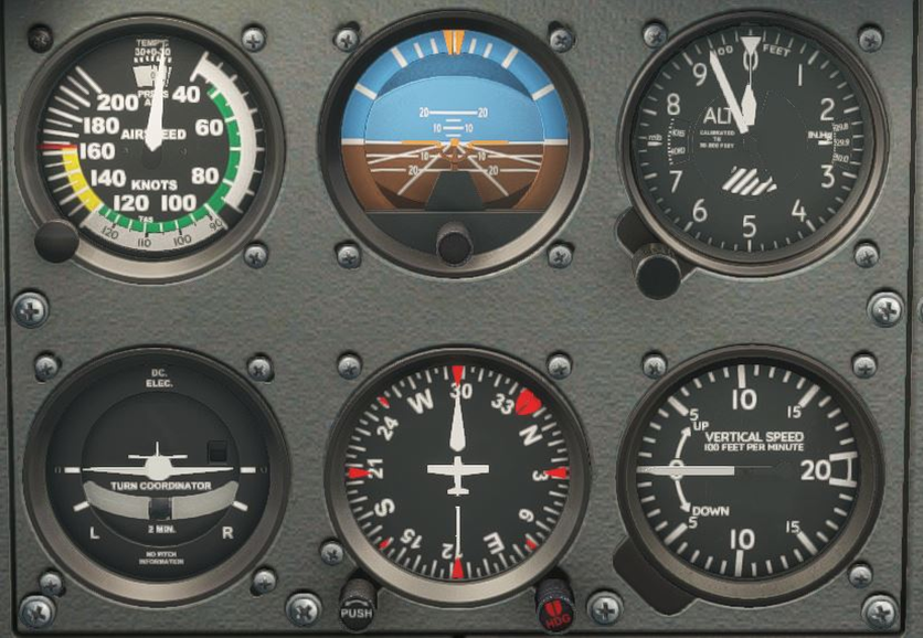
A classic artificial horizon. In the event of strong vibrations or acceleration, it tends to become misaligned. It is then necessary to calibrate it to the horizontal by pulling the knob "PULL TO CAGE".
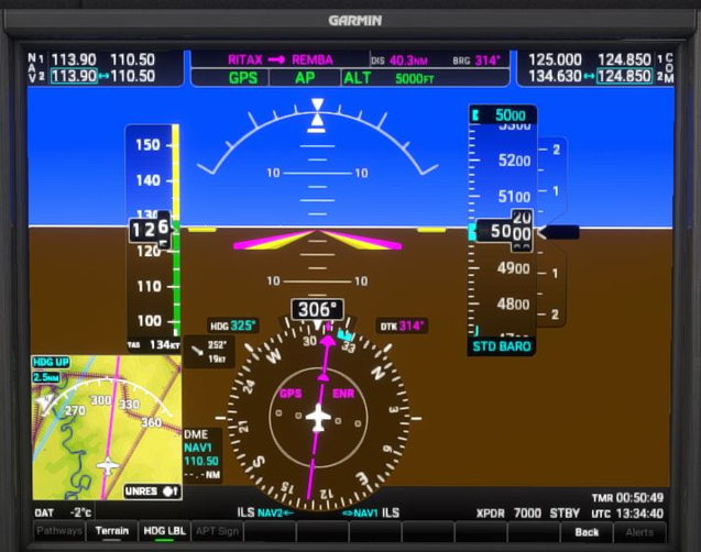
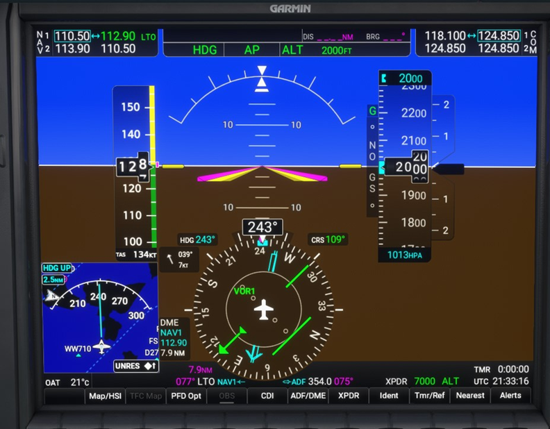
Here is the primary flight display of a Garmin 1000 avionics system now widely used in general aviation. This display consolidates the primary instruments, including a digital display of the artificial horizon (in the centre). The latter is powered by the AHRS and is not subject to mechanical errors..
1.2.2 Altimeter
The altimeter is a barometer that measures altitude relative to the reference pressure entered in the window (as we saw in section 1.1.3). It takes its source from a static port located outside the fuselage. The graduation is in feet (Ft), but it should be noted that some altimeters are also capable of displaying altitude in metres (for conversion when flying in certain countries that use the metric system).
The greater the deviation of the outside temperature from the ISA, the more the indicated altitude will diverge from the true altitude due to the effect of density. When the discrepancy becomes too significant, it is then necessary to apply a correction.
Here, a classic needle altimeter. The small needle indicates the thousands, the large hand the hundreds, and the triangle the tens of thousands of feet. The barometer shows 1013 hPa (or 29.9 inches). We are flying here at 5000 ft.
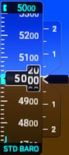
This time, the digital altimeter of the G1000. The barometer set to "STD BARO" means that we are flying at flight level FL050.
1.2.3 Vertical Speed Indicator (VSI)
This instrument, also known as a Variometer, indicates the rate of climb, that is to say, the rate of ascent or descent. It measures the variation in static pressure and displays it on a graduated scale in feet per minute (ft/min).
Its main drawback is its slowness, as the vertical speed display has a delay of about 5 seconds due to its design. More complex aircraft are generally equipped with a more advanced instrument (IVSI) that overcomes this error.
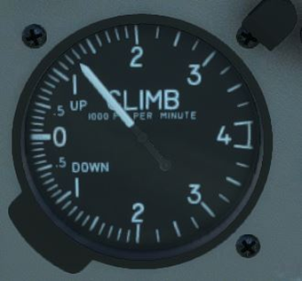
On the left, on this classic VSI, the vertical speed is here 750 ft/min in ascent. Note that the scale is logarithmic. Indeed, the graduations are more precise between -2000 and +2000 ft/min.

On the right, the digital VSI allows for an even more precise reading of the rate. We are climbing here at 1150 ft/min.
1.2.4 Air Speed Indicator (ASI)
Also called an Anemometer or Airspeed Indicator, it is a manometer that measures the dynamic pressure resulting from the difference between static pressure and total pressure. This reflects the speed of the aircraft relative to the mass of air. The instrument is powered by a probe installed in the airflow called a Pitot tube..
The speed indicator displays the indicated speed and serves as the primary reference for the pilot in terms of aerodynamics, regardless of atmospheric conditions. It is most often graduated in knots (kt) or kilometres per hour (km/h) and shows important flight domain references such as the flap operating range, stall speed, or overspeed.
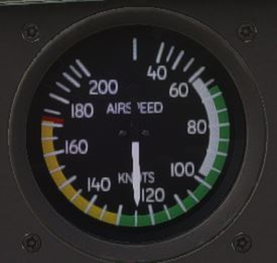
On the left, a classic anemometer graduated in knots (kt). Let us note the colour ranges :
- Green: Normal flight range
- Yellow: Flight range to avoid in turbulent air
- Red line: VNE (Velocity Never to Exceed)
- The white arc represents the usage range of the flaps
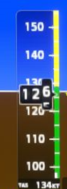
The equivalent on the G1000 can also calculate and display True Airspeed, here a TAS of 134 kt.
1.2.5 – Turn and Slip Indicator
It has the particularity of being made up of 2 instruments in 1.
The turn indicator is a gyroscopic system showing the direction and rate of turn. During instrument flight, the pilot refers to it in particular to ensure that the turn is executed at the standard rate of 3 degrees per second (Rate 1)..
The turn coordinator allows for the verification of flight symmetry through the pendular movement of a small ball immersed in a tube filled with liquid, and subjected to the forces of lateral accelerations..
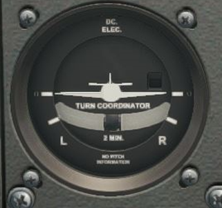
The aircraft model corresponds to the turn indicator. When one of the wings is aligned with the mark "2 MIN", it means that the turn is being made at the standard rate. The tube containing the ball is the turn coordinator. The pilot must ensure to keep it in the centre by using the rudder.
1.2.6 Magnetic Compass
As its name suggests, it displays the magnetic heading. Its operation is based on a magnetised compass rose floating in a liquid. This orients itself in the direction of magnetic North (Nm) and is graduated from 0 to 360°.
The magnetic compass is hardly used anymore as a primary means of navigation but serves as a backup instrument and reference for the recalibration of the course keeper..
Due to its design, it is subject to significant reading errors, particularly during turn and acceleration.
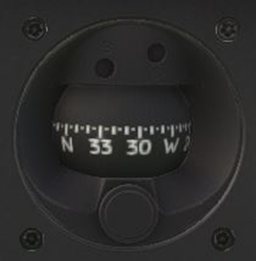
The last safeguard of navigation, the magnetic compass is present in all aircraft, including those equipped with the latest generation avionics.…
1.2.7 Directional Gyro (DG)
On the most basic IFR-approved light aircraft, the heading is still indicated by the heading indicator as found in VFR flight.
It is generally a compass driven by a gyroscope. Its reactivity and stability allow for a precise and almost instantaneous display of heading during a turn. Unlike a compass, it is not affected by acceleration..
Its main drawback is that it must be manually recalibrated by the pilot as it does not use an external reference and ends up drifting (about 12°/hour): this is referred to as "precession". This is due both to the mechanical friction of the instrument and to the rotation of the Earth.
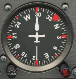
The heading indicator appears as a simple compass rose. We are following a magnetic heading (Cm) of 298°. It recalibrates using the "PUSH" knob.
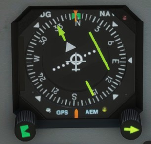
1.2.8 Gyromagnetic Compass (HSI)
From light aircraft to airliners, the HSI (Horizontal Situation Indicator) is the standard navigation instrument for IFR flight and is much more comprehensive and sophisticated than those mentioned previously..
Like the Heading Indicator, it operates using a gyroscope but is this time slaved to a flux valve that continuously aligns it with magnetic North (Nm). Additionally, in modern glass cockpit avionics, the source is no longer a gyroscope, and the information comes from the AHRS system or inertial reference units..
Its main advantage is therefore that it does not suffer from the phenomenon of precession and displays a reliable heading at all times. It also has the benefit of being able to integrate the display of VOR or ADF radio navigation aids, and even to be coupled with a GPS/RNAV system.V.
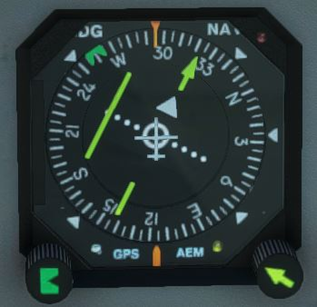
Here, a classic HSI. The heading is 295°. The yellow needle is the VOR indicator (which we will cover in a following chapter).
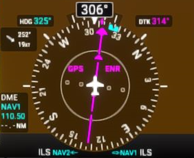
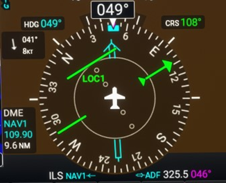
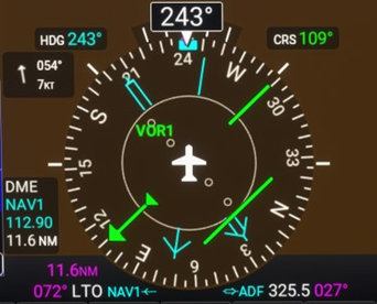
This time, a digital HSI, still on the G1000. Computer management allows for the integration of other useful information for navigation, such as here the speed and direction of the wind (252° / 19Kt).
1.3.Instrument flying
1.3.1 Selective Radial Scan
In IFR flight, the pilot relies exclusively on the instruments (notably the primary instruments we mentioned earlier) to control the aircraft, regardless of external visibility.
It is neither possible nor desirable to look at all the instruments at once. For optimal efficiency, the instruments are read in a defined sequence according to the phase of flight: this is selective radial scanning. This method is based on 3 principles :
Selection of instruments:
- Primary instruments (AI, ASI, HSI, Altimeter, Turn indicator, VSI)
- Secondary
Radial: The visual scanning generally starts from the primary instruments, then moves to the secondary instruments before returning to the primary instruments. In the vast majority of cases, the scan begins from the AI.
Time distribution. A typical scan is distributed as follows :
- 80% of the time : control instruments
- 15% of the time: performance instruments
- 5% of the time: positioning instruments
1.3.2 Straight and level flight
Primary instruments: AI, ALT, HSI
Scan:
- 80% ADI
- 15% ALT and HSI
- 5% Secondary instruments
Method:
- Maintain altitude by adjusting the attitude.
- Maintain heading while keeping the wings level.
- Maintain speed by adjusting the power.
- Once stabilised, adjust the trim.
- Keep the ball centered with the rudder.
- In the event of a speed variation, adjust the attitude and trim if necessary.
PERFORMANCE = ATTITUDE + POWER
1.3.3 Turn
Primary instruments: AI, ALT, Turn indicator, HSI
Scan :
- 80% ADI
- 15% ALT, Turn Indicator, HSI
- 5% Secondary instruments
Method:
- Turn towards the desired side by banking the wings at the standard rate.
- Maintain speed by increasing power.
- Maintain altitude by increasing the pitch.
- DO NOT TRIM during the turn.
- Keep the ball centered with the rudder.
- Anticipate the exit of the turn at the desired heading.
Number of degrees to anticipate = bank angle°/3
1.3.4 Climh and Descent at constant speed
Primary instruments: AI, ASI, HSI
Scan :
- 80% ADI
- 15% ALT, ASI, HSI
- 5% Secondary instruments
Method:
- Adjust the power to the desired value.
- Adjust the pitch until reaching speed.
- Trim.
- Keep the ball centered with the rudder.
- Correct speed by adjusting the attitude.
- Trim again if necessary.
CONSTANT SPEED + FIXED POWER > RATE
1.3.5 Climb and Descent at constant rate
Primary instruments: AI, VSI, HSI
Scan :
- 80% ADI
- 15% VSI, HSI
- 5% Secondary instruments
Method:
- Adjust the pitch until the desired rate is reached.
- Adjust the power to maintain the desired speed.
- Trim.
- Keep the ball centered with the rudder.
- Correct rate by adjusting pitch.
- Correct speed by adjusting the power.
- Trim again if necessary.
CONSTANT RATE + CONSTANT SPEED > POWER
1.3.6 Vertical Navigation
To determine the required rate of climb or descent, the instrument procedures (approaches, departures) generally specify a gradient.
It is the ratio (in %) between altitude and distance. For reference, 1% corresponds to :
- 1 metre of altitude for every 100 metres travelled.
- 60 ft of altitude per 1 nm of distance travelled.
Rate (ft/mn) = GS (kt) x Gradient (%)
Example :
We want to descend with a gradient of 5% at a ground speed of 100 kt
- 100 x 5 = 500
- We should descent at 500 ft/mn.
1.3.6 Drift correction
The wind is omnipresent in the atmosphere and increases with altitude. Therefore, the pilot must constantly be aware of its effect on the aircraft's trajectory, particularly that of crosswind (X-Wind)..
To do this, it is essential to know the wind correction angle (WCA) to apply in order to fly the heading (HDG) that allows for following the desired track (TRK)..
The GPS is by nature capable of knowing the route (TRK) as it determines our position on the ground; when we do not have it on board, we must rely on conventional instruments..
With only an HSI or a DG as a reference, here is a quick technique to apply in flight to estimate the necessary correction:
1.Determine the crosswind component (X-Wind) by virtually dividing the HSI/DG according to the Two Thirds Rule.
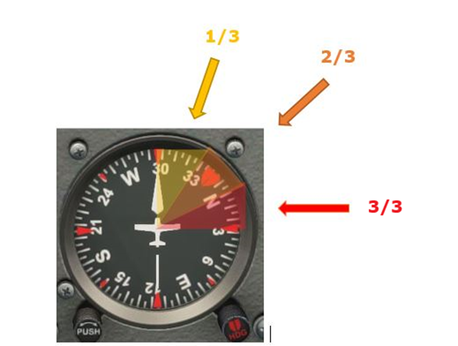
IIt is a matter of representing each quarter of the rose in 3 equal parts.
In the diagram above, if the wind comes from a direction between :
- 300° and 329°, we take into account 1/3 of the wind speed.
- At 330° and 359°, we take 2/3.
- 360 and 029°, we take 3/3.
- Etc... we continue like this depending on the direction of the wind.
2. Calculate the wind correction angle (WCA) using the following formula:
WCA = X-Wind / (TAS/60)
3. Add or subtract the WCA from the current heading as appropriate. To compensate, you need to "head into" the wind to counter its effect..
Example
We want a Track (TRK) of 300° at a true airspeed (TAS) of 100 kt. The published wind chart indicates a wind from 340° at 21 kt at our altitude. What is the estimated correction to apply?r ?
- X-Wind > 2/3 of 20 kts = 14kts
- WCA= 14/ (100/60)=100/60=8.4 (rounded to 8°)
- HDG= 300-8 = 292°
We must therefore fly on a heading (HDG) of 292° in order to follow our track (TRK) of 300°.
The reference wind will be that published in the weather forecasts we obtained during the flight preparation, or that transmitted by air traffic control..
1.3.8 Effect of the wind on speed
As with direction, the wind affects speed. A tailwind component (HD) or headwind component (TL) can significantly increase or alter our speed. As a reminder, let us remember :
- No Wind : TAS=GS
- Tailwind : GS > TAS (on va + vite)
- Headwind: GS < TAS (on va - vite)
The estimation of a suitable ground speed is essential in terms of flight planning as it allows, among other things, to determine the flight time, and therefore the necessary fuel.
EIn flight, the GPS continuously displays the ground speed (GS). In its absence, using the two-thirds rule allows for an estimation, but this time by reversing the values. :
- 1/3 > 3/3
- 2/3 = 2/3
- 3/3> 1/3
Example (See diagram in 1.3.7)
We are flying at a true airspeed (TAS) of 150 knots and the wind is still from 010° at 30 knots. What is our ground speed (GS)?
- HD = 1/3 of 30 kt = 10 kt
- GS= 150 + 10 = 160 kt
Our ground speed is therefore 160 knots.
2.Radio Navigation aids
2.1 ADF/NDB
This is the oldest means of radio navigation still in service. It is essential to clearly distinguish between ADF and NDB beforehand. :
The ADF (Automatic Direction Finder), also known as a Radio Compass, is the receiving instrument installed on board the aircraft..
The NDB (Non-directional Beacon) is the ground-based transmitting beacon.

An NDB as represented by the symbology of Jeppesen charts. It is designated by a 2-letter identifier, here "GU" (Brest Guipavas) and transmits on the frequency 338KHz. The small bars correspond to the Morse code that allows it to be identified by radio..
2.1.1 Principle
The NDB is a non-directional radio beacon, meaning it broadcasts a signal in all directions and with the same power, with a transmission frequency ranging from 190 to 1750 kHz (medium frequency).
The range varies depending on the type of beacon:
NDB standard: 25 to 75 nautical miles
Locator (final approach): 10 to 25 nm
The signal detection operates on the principle of radiogoniometry, that is to say, by determining the direction of arrival of the electromagnetic wave. This is referred to as Magnetic Bearing, which is itself divided into 2 types:
QDM : Bearing in approach towards station (TO)
QDR : Bearing away from the station (FROM)
Relative Bearing : Angle between the axis of the aircraft and the direction towards the station.
The NDB has the advantage of relative ease of use and a still significant presence in remote areas where VOR and ILS are not available. On the other hand, it has a number of disadvantages affecting the reliability of the signal :
- Average accuracy
- Night effect
- Effect of relief
- Effect of storms
2.1.2 Instrument
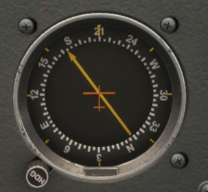
The classic ADF is presented in the form of a compass rose equipped with a directional needle that constantly points towards the station. It should be noted that unlike an HSI/DG, the instrument is not powered by a gyroscope, which means that the heading (HDG) must be manually aligned with the aircraft to determine the bearing.
In more complex cockpits, the ADF is integrated with another instrument: the RMI (Radio Magnetic Indicator). Unlike the classic ADF, it automatically and constantly indicates the heading (HDG) of the aircraft. Additionally, the RMI also contains the VOR needle..

A traditional ADF receiver and its frequency selection box.
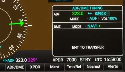
On the G1000, the ADF needle (in blue) is integrated into the HSI. The ADF frequency is selected from a menu located on the PFD..
2.2 VOR
The VOR is the most common radio navigation beacon on which conventional procedures are based. Subsequent to the NDB, it is frequently associated with a DME (Distance Measuring Equipment).
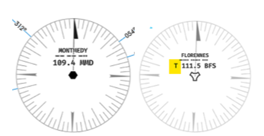
On the left, a classic VOR. The identifier consists of 3 letters. The VOR MMD is available on the frequency 109.4MHz. As with an NDB, it can be identified by the pilot by listening to its Morse code..
On the right, the TACAN BFS located near the military airfield of Florennes, identifiable by its specific symbol and the letter "T" before the frequency.
2.2.1 Principle
The VOR beacon transmits in the very high frequency (VHF) range of 108.00 to 117.95 MHz. There are 3 types of VOR. :
VOR en-route: used to follow airways with a range of approximately 200 nm.
VOR terminal: located near aerodromes and associated with instrument departures and approaches with a range of approximately 50 nm.
VORTAC: a VOR associated with a military TACAN (Tactical Air Navigation System) beacon.
The VOR is represented by 360 beams radiating from the beacon called Radials. The angle between the aircraft and a radial allows for the determination of the magnetic bearing relative to the station.
We get closer to or further away from the station by following a course that leads away. (Outbound): the QDR or in rapprochement (Inbound) : the QDM.
Compared to an ADF, the VOR enjoys better accuracy and can provide distance information (when coupled with a DME).
On the other hand, ground installations are more expensive to implement and the error due to the terrain is always applicable.
2.2.2 Instrument
The VOR receiver allows the determination of the radial on which the aircraft is located and consequently to track it either moving away from or towards the beacon, indicated by a TO/FROM indication (and/or an arrow). Depending on the aircraft's equipment, VOR reception can be found in various types of instruments.:
CDI (Course Déviation Indicator) : Still common on the most basic IFR-approved aircraft and consisting of a vertical deviation bar in a heading roses.
HSI : The most widespread and coupled with the heading indicator (HDG).
RMI : In addition to the main receiver and coupled with the ADF receiver. Like the latter, it simply points towards the station.
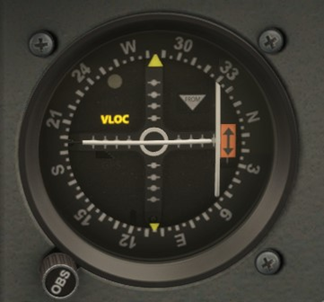
On the CDI, the OBS knob is turned until the desired radial (Course) is displayed. The triangle indicates either TO or FROM depending on whether the direction brings us closer to or further away from the station.
More effective for navigation, the HSI displays the heading alongside the VOR radial, adjustable with the right knob (Course, here represented by a yellow arrow).
The advantage of the digital HSI is that it is possible to add a multitude of information (RMI, DME, wind, etc…) for a better representation of the situation.
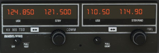
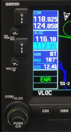
The VOR frequency is selected in the NAV section (on the right) of the radio box. In this example, the frequency 110.50 is active while 114.90 is on standby. The COMM section (on the left) relates to the communication radios.
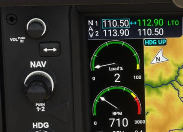
Following the same principle, the frequency selection menu for radio navigation on the G1000.
2.3 DME
Le DME (Distance Measuring Equipment) allows for the determination of the distance between the aircraft and the ground transmitter and is essential for the execution of numerous instrument procedures.
The "D" in front of the frequency indicates that the VOR is coupled with a DME. This is referred to as VOR DME.
When an ILS is associated with a DME, it then becomes an ILS DME.
2.3.1 Principle
The distance is known by measuring the time taken by the radio signal to make the round trip between the aircraft and the station. The transmission frequency is within the UHF range of 962 to 1213 MHz..
In the vast majority of cases, the DME is generally linked to a VOR (or an ILS or a TACAN) whose distance is automatically displayed once the frequency is shown. Consequently, the range of the DME corresponds to that of the beacon in question.
2.1.1 Instrument
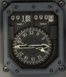
The main information provided by the DME is naturally the distance to the ground station and is displayed in nautical miles (nm).
There are mainly 2 types of DME receivers :
- The independent DME unit can, in addition to displaying the distance, calculate the flight time required to reach the station, as well as the ground speed (GS). Note that this data is only usable if the aircraft is flying straight towards the station. Now obsolete, this type of receiver is mainly found on older aircraft, particularly as a complement to a CDI.
- The integrated receiver is directly installed on the VOR receiver (HSI or RMI) and provides the pilot with better situational awareness.
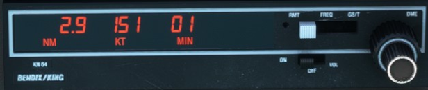
En In addition to the distance, the independent DME unit traditionally displays ground speed (GS) and the time required to the station.
The DME display is shown here on the Garmin GPS screen.
In addition to pointing towards the VOR, the RMI contains a DME for each of the 2 VOR radios.
On an HSI, the DME is part of the information integrated into the display.
2.4 ILS
L’ILS (Instrument Landing System) sstill have to this day the most efficient radionavigation means used for approach and landing.
2.4.1 Principle
The aircraft is guided horizontally and vertically towards the runway during the final approach by 2 distinct radio electric signals :
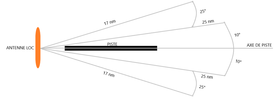
- The runway alignment beacon or Localizer (LOC) provides horizontal guidance, that is to say, the direction towards the runway through a series of antennas installed along the runway axis. It transmits in VHF between 108.00 and 111.95 MHz and is usable within an arc of 35° on either side of the approach axis, with an approximate range of 25 nm.
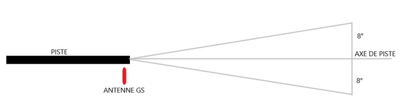
- The Glide Path (GP) or Glide Slope (G/S) provides vertical guidance in the approach path. Although it transmits in UHF, the signal is displayed in conjunction with the LOC when its frequency is selected. The slope (FPA) is generally 3° but can vary from one approach to another. The signal is emitted by antennas located at the height of the touchdown zone and covers an arc of 8° around the approach axis over a distance of 10 nm.
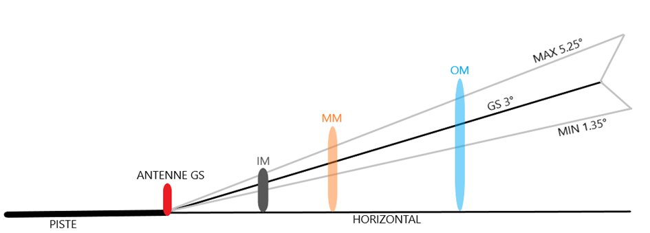
Markers : These are markers installed on the ground along the ILS path. They emit a vertical beam that triggers a tone and a light signal in the cockpit when passing vertically. There are 3 types of markers depending on the distance from the runway :
- Outer Marker (OM): 4 to 7 nm
- Medium Marker (MM) : 0.5 to 0.8 nm
- Inner Marker (IM) : runway threshold
Their purpose is to provide distance information while cross-checking altitude on the descent profile at time T. With the widespread adoption of DME, radio beacons have become obsolete and have largely disappeared from approach procedures. Those that still exist today are generally OM, with MM and IM remaining in very small proportions.
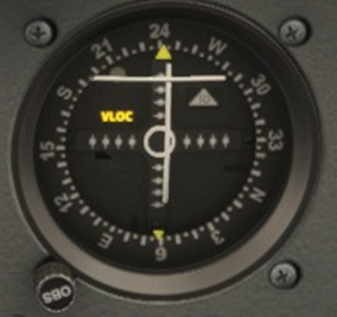
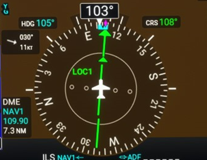
In the case of a CDI displaying an ILS, the central bar of the VOR (VLOC) then becomes that of the LOC. The GS corresponds to the horizontal bar.
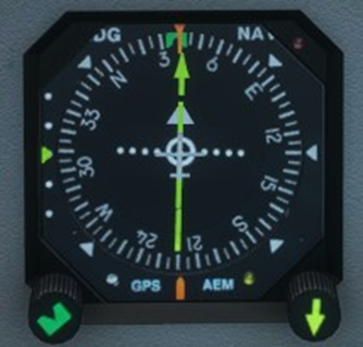
On the left of the instrument, the descent profile display consists of a scale and a pointer (here a yellow triangle) representing the GS. As with the CDI, the LOC has replaced the VOR radial.
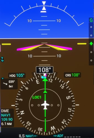
The GS is sometimes located opposite the Artificial Horizon (AI), as in the case of the G1000 (the scale is on the right in this case).
3.Navigation
3.1 VOR Navigation
In this lesson, we will focus exclusively on navigation using the HSI as the primary instrument, possibly supported by the RMI. Indeed, the vast majority of aircraft equipped for instrument flight are fitted with it, whether it is classic analogue instrumentation or a glass cockpit.
3.1.1 Position
To know your position relative to a selected VOR beacon, simply turn the CRS knob until the needle is centred. You can then read which radial you are on at that moment.
Note: On the HSI, the tail of the needle continuously indicates the current radial.
Now, let us interpret the situation depending on whether we want to get closer to or move away from the station :
- INBOUND : We turn the Course (CRS) knob until the needle is centred AND the green arrow pointing towards the station is displayed. The current radial corresponds to the tail of the needle.
- OUTBOUND : We turn the Course (CRS) knob until the needle is centred AND the arrow points towards the opposite of the station. The current radial corresponds to the tip of the needle.
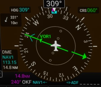
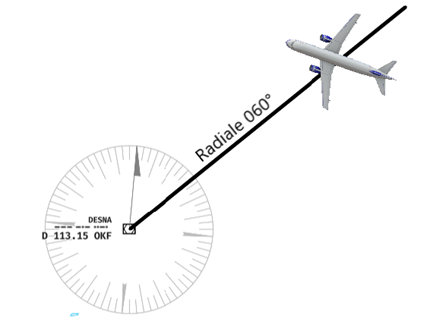
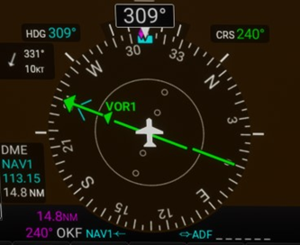
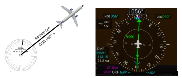
3.1.2 QDM/QDR
Considering the situation presented in chapter 2.5.1, let us revisit the 2 scenarios.
- QDM : To fly on the 60° radial inbound, we must then turn in the direction the needle points, namely a heading (HDG) of 240°. We then head towards the VOR on a QDM of 240, or 60° INBOUND radial.
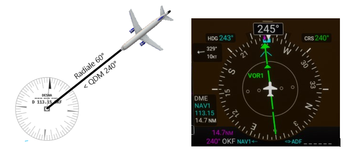
- QDR : To fly on the same radial 60° outbound, we turn to heading 60°. We are departing from the VOR on a QDR 060° or radial 60° OUTBOUND.
3.1.3 Radial interception
In this section, we will see how to intercept a predetermined VOR radial as is the case in IFR procedures. In order to execute this, it is essential to determine an appropriate interception heading based on your current position and the radial to intercept.
The interception heading must allow for rejoining the radial at a sufficient angle: the attack. There is no imposed rule, except that the attack is generally understood to be between 20° and 90°..
However, to have a precise idea of an appropriate interception course, we can refer to the following formula :
Attack° = (Current radial – Desired radial) x 2
In summary, the greater the difference between the current radial and the desired radial, the greater the necessary attack will be, without exceeding 90°.
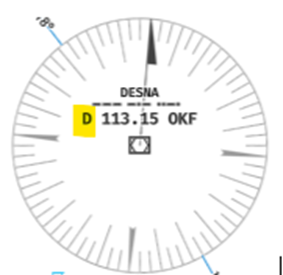
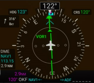
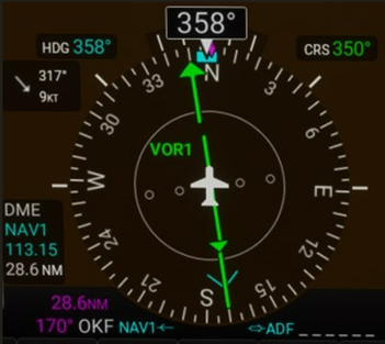
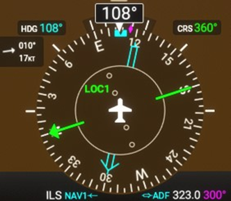
- INBOUND : On a heading of 089°, the tail of the RMI needle (in blue) indicates that we are currently on the radial 350°. We wish to intercept the radial 300° INBOUND to join the VOR of Desna (OKF – 113.15).
1. We select the desired radial using the CRS knob, here the 300° INBOUND radial, which corresponds to a QDM of 120°. We notice that the radial is to our right.
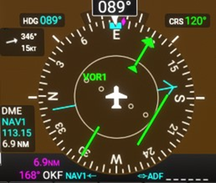
2. To intercept the radial, we will take an interception heading corresponding to a 90° attack towards the radial.
3. When the needle starts to move towards the centre, we turn left to QDM 120° without exceeding the standard rate of turn. We then follow the radial as desired.
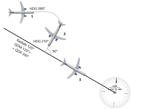
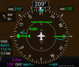
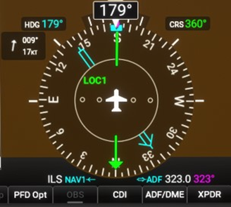
- OUTBOUND : On a heading of 330°, the tail of the RMI needle (in blue) indicates that we are currently on the 330° radial. We wish to intercept the 350° OUTBOUND radial from the Desna VOR (OKF – 113.15).
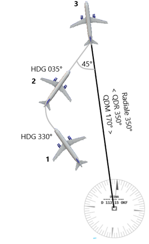
- Select the desired radial using the CRS knob, here the 350° OUTBOUND radial, which corresponds to a QDR of 350°. We can see that the radial is to our right.
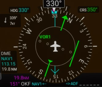
2. To intercept the radial, we will take an interception heading corresponding to a 45° attack towards the radial.
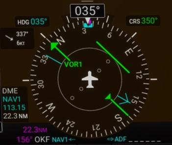
3. When the needle starts to move towards the centre, we turn left to QDR 350° without exceeding the standard rate of turn. We then follow the radial as desired.
3.1.4 Passing overhead
Passing overhead of a VOR beacon is indicated by several signs :
- Distance (when a DME is available). Note that the distance displayed on the DME is the slant range distance between the aircraft and the station, meaning it takes into account both the ground distance AND the height (AGL).
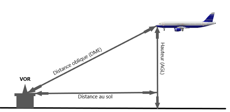
Knowing that 6000 ft = 1 nm, the distance displayed on the vertical DME in relation to the height will be as follows :
L’aiguille du RMI tilt of 180° backwards.
- L’indication TO/FROM (where the arrow) of the instrument moves from TO to FROM, confirming that we have indeed transitioned from the phase of approaching (INBOUND) to that of distancing (OUTBOUND).
After passing vertically over the station, to intercept an outbound radial, a 30° bank is necessary.
3.1.1 Wind effect
During the interception of a radial, the interception heading must be corrected for the current wind.
- Without GPS: In order not to be burdened with complex calculations during the flight, a correction of +/- 10° will be conventionally applied depending on the wind direction if the wind does not exceed 30 kt. Beyond 30 kt, it is necessary to increase the correction..
- With a GPS: You just need to correct the heading (HDG) to follow the desired track (TRK).
To follow the radial, we adjust the heading (HDG) to compensate for the crosswind (X-Wind) as we saw in 1.1.4.
3.2 ADF Navigation
On the G1000, the RMI is directly integrated into the HSI. It is possible to display the ADF on one of the 2 needles. As traditionally the ADF is represented by a double needle, we will preferably use this one (BRG 2) for navigation.
3.1.1 Position
The needle of the instrument (here the blue double needle) constantly points towards the NDB beacon. The tail of the needle indicates which QDM we are on; conversely, the arrow shows the QDR.
3.1.1 Interception
As with the interception of a VOR radial, the interception of a bearing from/to an NDB requires the use of an interception heading. This will be a maximum of 90° and can be estimated using the following calculation :
Attack° = (Current QDM – Desired QDM) x 5
In the case of a vertical passage over the NDB, the interception of the QDR is generally made with a 30-degree angle of attack.°
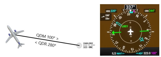
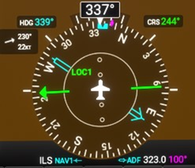
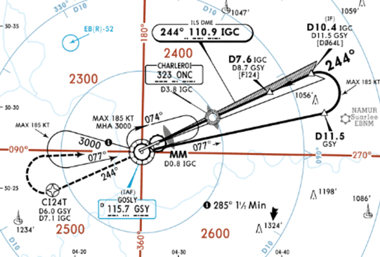
- INBOUND : On a heading of 337°, we wish to join the NDB of Charleroi (ONC – 323 kHz) on a QDM of 120°.
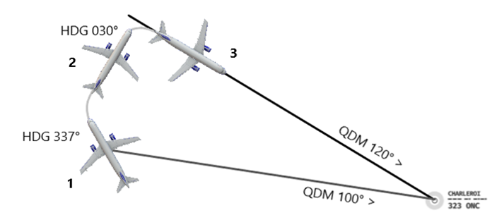
1. Currently on a QDM of 100°, we observe that the QDM of 120° we are looking for is located 20° to the right of our current QDM.
2. We turn right so as to have an attack angle of 90° towards the QDM 120°.
3. Once the needle of the ADF approaches 120°, we turn right to join and follow the QDM 120°.
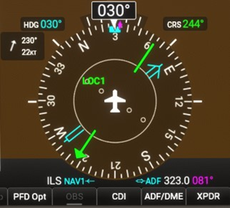
- OUTBOUND : After passing overhead the marker, we wish to move away from it by following a QDR of 150°.
1. As we move away from the NDB, the QDM 120° becomes the QDR 300°. From this position, the QDR 150° is therefore 50° to our right.
2. We are taking a heading of 180° to "attack" at an angle of 30°.
3. When the ADF needle approaches 150°, we turn left to intercept and follow the QDR 150°.
3.2.3 Wind effect
During the interception of a QDM/QDR, the wind corrections are identical to those applied for the interception of a VOR radial (See 3.1.5).
4.Procedures
4.1 Holding Pattern
The holding pattern, commonly referred to as Holding, is an in-flight procedure designed to keep an aircraft circling around a fixed point (VOR, ADF, Waypoints, etc…).
The holding pattern is generally imposed by air traffic control during descent or approach due to traffic, but it can sometimes be at the pilot's discretion (for example, to wait for an improvement in the weather), or it may also be imposed during an approach procedure or go-around..
4.1.1 Principle
It takes the form of a racetrack whose trajectory involves moving away for a given time or distance from a buoy and then returning parallel on a published course towards it. :
- STANDARD (on the right)
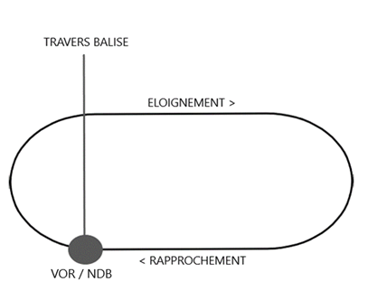
- NON-STANDARD (on the left)
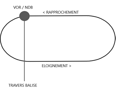
The outbound time is 1 minute, unless otherwise indicated by time or DME distance..
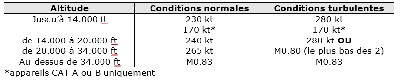
The maximum speed in a holding pattern is defined by the ICAO document Doc 8168 Vol 1:
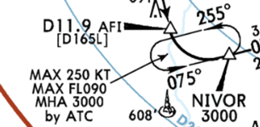
The altitude is either imposed by the controller or published :
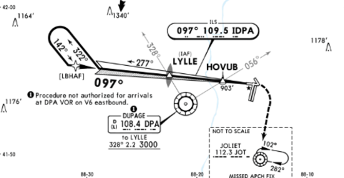
4.1.2 Entries
Depending on the arrival sector towards the station, 3 types of entry are possible to join a waiting circuit. Here is the diagram applicable to a standard circuit :
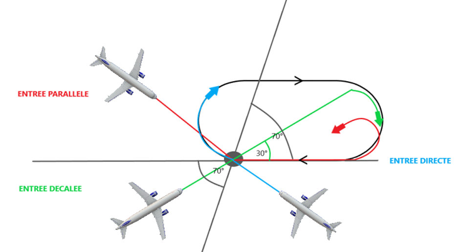
- Parallel Entry : After reaching the station, we take the outbound heading for 1 minute, then turn to return to the station and subsequently enter the holding pattern.
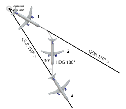
- Offset/Teardrop Entry : After reaching the station, we take a heading of 30° outbound within the circuit for 1 minute, then we turn to return to the station and subsequently enter the holding pattern.
- Direct Entry : After reaching the station, we turn to enter the holding pattern.
4.1.3 Wind effect
In order to correct the effects of the wind, it is necessary to apply the following correction techniques :
- Headwind/Tailwind: +/-1 second during the outbound phase per knot of wind component.
- Crosswind: If available, follow the Track (TRK) with the GPS. DOUBLE the correction on the Outbound during the first minute, then return to a standard correction until the end of the outbound leg.
This is necessary in order to avoid being too "pushed" or, on the contrary, "held back" by the wind when joining the convergence branch..
Example :
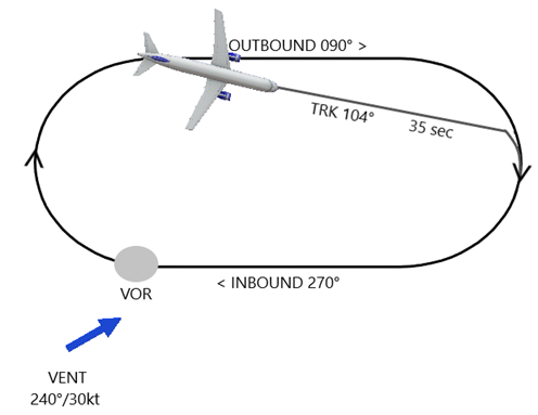
We need to enter the standard holding pattern towards the VOR with an inbound course of 270°.
Our true airspeed (TAS) is 120 kt.
The estimated wind is 240° at 30 kt.
Once we have passed the station, we turn right to follow an outbound course of 90°. Based on the GPS information, we will correct the time and the track (TRK) of the distance.t :
- A ground speed (GS) of 145 knots, therefore 25 knots of tailwind. We need to subtract 145-120= 25 seconds from the 1-minute departure time, which is 35 seconds..
- A heading (HDG) of 97°, therefore a correction of 7°. We need to double the wind correction, 7 X 2 = 14°, so we should follow a track (TRK) of 104°.
4.2 Reversal Procedure
The published instrument procedures, mainly the approach procedures, contain different types of turns that should be executed according to defined methods..
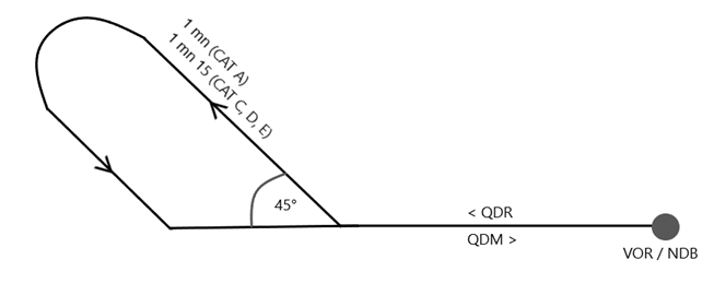
4.2.2 Procedure Turn 45°/180°
On a QDR, at the point of the published reference, we turn 45° for 1 minute before turning 180° to intercept the QDM.
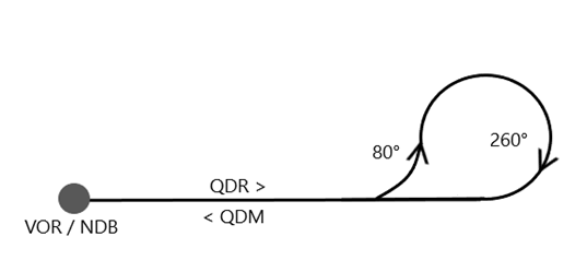
4.2.3 Procedure Turn 80°/260°
For a QDR, at the point of the published reference, we turn 80° and then 260° in the opposite direction to intercept the QDM.
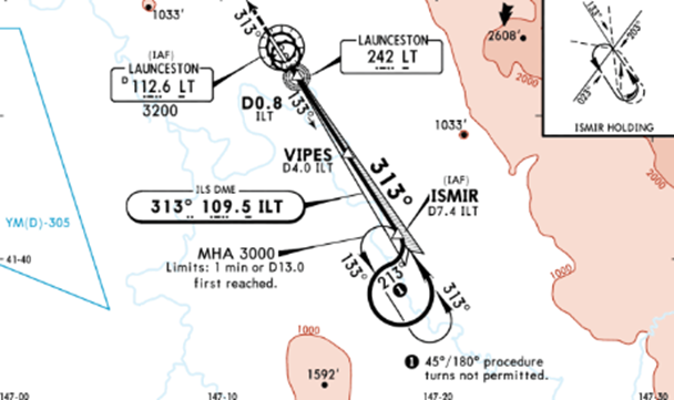
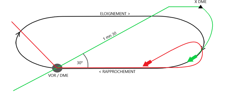
4.2.4 Racetrack
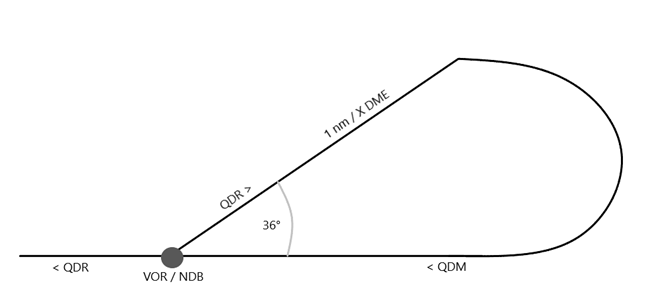
Very similar to a classic holding pattern, there are however some nuances depending on the type of entry:
- Teardrop/Offset: After passing overhead the station, we turn 30° for a maximum of 1 minute 30 seconds before flying away parallel to the QDR until the prescribed DME distance. We then turn to intercept the QDM..
- Parallel: After passing overhead the station, we return towards it by intercepting the QDM.
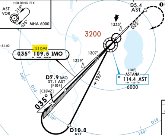
4.3 DME Arc
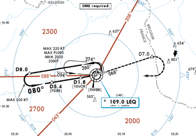
This procedure requires flying around a beacon at a constant distance, usually before intercepting the final approach path. The reference DME may be that of a VOR or an ILS according to the published procedure..
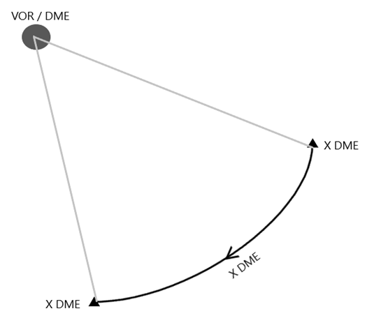
Before following the DME Arc, we need to calculate a distance of anticipation from the station at which we will need to start turning (at the standard rate of turn) :
ARC DME Distance + (TAS/200)
The goal is to maintain a constant DME distance; the technique involves turning in such a way as to keep the RMI needle at 90° to our current heading. In practice, we turn 10° for every 10° of radials crossed until the exit..
Example :
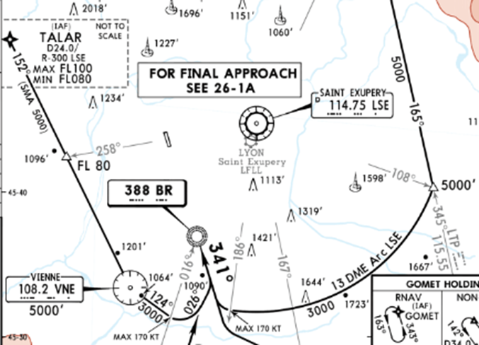
To intercept the DME ARC located 13 nm from the VOR of Saint Exupéry at a true airspeed of 120 kt (TAS), after passing the radial 108°, we need to start turning at: 13 + (120/200) = 13.6
We must therefore start to turn to follow the DME ARC when our DME indicates 13.6 nm.
The approach chart indicates that we must exit the DME ARC at the intersection of my radial 186°, and then continue on the QDM 341° towards the NDB BR.
5.Approaches
As we saw in part 2, the approach, which is the final phase of the flight leading to the runway, uses ground-based radio navigation aids (VOR, NDB, ILS). We then refer to conventional approaches..
Since a more recent time, there are parallel PBN approaches, initially referred to as RNAV (GNSS) approaches. We will not cover these in this course as they are the subject of a specific course that we have previously published.
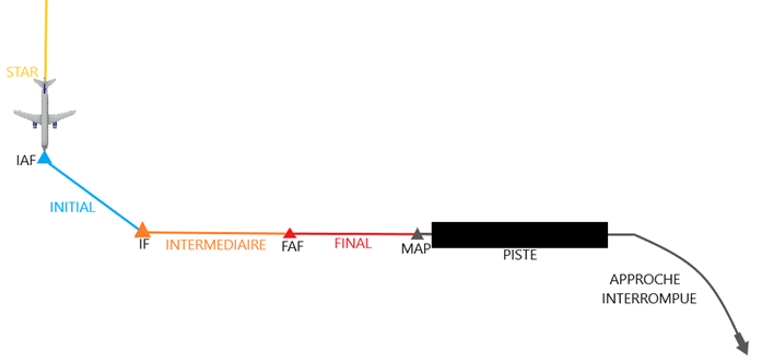
5.1 Segments
The approach is divided into 5 distinct parts called "segments" separated by points where the Minimum Obstacle Clearance Altitude (MOCA) varies :
STAR (Standard Arrival Route) : The procedure linking the En-route part to the approach procedure.
- MOCA : 1000 ft
- IAF : Initial Approach Fix
Initial : The start of the procedure leading to the selected approach.
- MOCA : 1000 ft
- IF : Initial Fix
Intermediate : The last leg before the final approach.
- MOCA : 500 ft
- FAF/FAP : Final Approach Fix / Point
Final : The final descent trajectory to the runway (ILS for example).
- MAP : Missed Approach Point
Missed Approach : The published procedure to follow in the event of a go-around during the final approach.
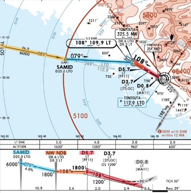
Example :
The approach segments of the ILS Y 11 at Nouméa (NWWW) are divided as follows :
- STARS from SOTAL descending to 6000ft
- Initial Approach from SAMID (IAF) descending to 1800 ft
- Intermediate Approach from NW (IF) at 1800 ft
- Final Approach since D5.7 where we intercept the G/S
- Missed Approach since D0.8 (MAP)
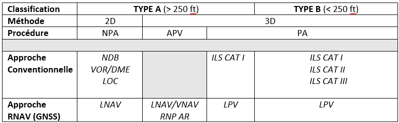
5.2 Classification
The latest ICAO regulations define approaches in 2 types based on decision height (DH) :
Type A ( > 250 ft)
Type B ( < 250 ft)
At the same time, they are also defined according to the approach method :
2D - lateral guidance
3D - lateral and vertical guidance
The different approach procedures are thus classified:
NPA - Non Precision Approach
APV - Approach with Vertical Guidance
PA - Precision Approach
5.3 Minimums & Categories
5.3.1 Minimums
This published approach specifies the altitude or height to which the pilot can descend without seeing the runway: these are the approach minima. Without visibility of the facilities, he is compelled to discontinue the approach.
Different types of minima apply depending on the type of procedure :
MDA - Decision Altitude
DA - Decision Altitude
DH - Decision Height
CFDA - Continuous Descent Final Approach

In parallel with the decision altitude/height, approaches impose minimum visibility requirements to be authorised to begin the approach.
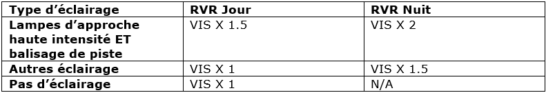
5.3.2 Visibility / RVR
EIn parallel with the decision altitude/height, minimum visibility requirements are also established to be authorised to begin the approach. There are two closely related but distinct concepts for measuring visibility :
- VIS - Visibility : The distance from which it is possible to distinguish an unlit object. It can be either horizontal or vertical..
- RVR - RRunway Visual Range: The distance from which the pilot can see the runway installations (runway markings or approach lights). The RVR, when available, generally allows for more advantageous minima than with a simple visibility indication.
By convention, the RVR can be estimated based on visibility according to the conversion table below :
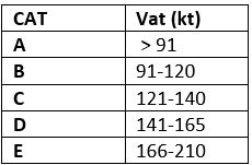
5.3.3 Approach categories
The approach minima also depend on the category of aircraft. This is defined by the approach speed at the runway threshold (Vat) under the following conditions: stall speed X 1.3 at maximum landing weight.
Vat= Vs X 1.3 à MLM
Example :
In the section concerning the minima, these are indicated according to the type of procedure and the category of aircraft :
- LPV Approach: Category A and B aircraft have a DA of 858 ft and 868 ft for those in Category C.
- LNAV/VNAV approach: The minima are 968 ft (A), 978 ft (B), and 988 ft (C).
- LNAV: No category is specified, which means that the MDA of 1180ft applies to all categories of aircraft.
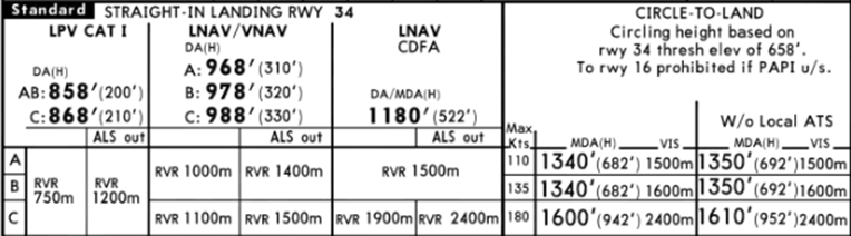
The RVR is also published according to the category of aircraft, but also according to the availability of certain approach aids. For example, for an LPV approach, the RVR is reduced from 750 to 1200 m if the approach lights (ALS - Approach Lighting System) are out of service.
- Circle to Land: For category A, the MDA is 1340 ft and the minimum visibility is 1500 m. The MDA increases to 1350 ft if no air traffic control service (ATS - Air Traffic Service) is available, etc…
5.3.4 Approach Ban
According to the regulations, it is prohibited to continue an instrument approach beyond the following points if the last reported visibility/RVR is below the minimum :
- PA : Du FAP ou balise extérieure (OM)
- NPA : En dessous de 1000 ft AGL
Si tel est le cas, le pilote doit interrompre l’approche sans même descendre jusqu’à l’altitude/hauteur de décision publiée.
5.4 Types deApproches
5.4.1 Precision approach
The Category I ILS is the most common and the standard among this type of approach procedure. It allows descent to a DH of 200 ft without visibility with an RVR/VIS of 550 m..
5.4.1.1 Preparation
Once the approach procedure has been assigned by air traffic control, it is necessary to make a point in a briefing that must contain the following elements :
Weather
NOTAM
Fuel: reserve + minimum diversion
Avion : Status / limitations + performance
Approach charts: verification and reading of appropriate approach procedures (STARS + ILS + Airport) :
- Minimas (DA(H)/RVR/VIS
- Route : approach + missed approach
- Radio navigation aids / frequencies + course (CRS)
- MSA (Minimum Safe Altitude)
- Runway marking / approach lights
- Exit taxiway
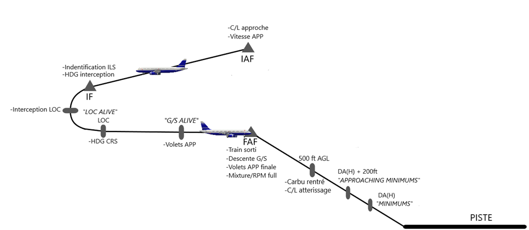
5.4.1.2 Execution
-When passing IAF :
- Perform approach checklist.
- Reduce speed to 120 kts.
-When passing IF / interception heading to the LOC:
- Check receipt of the ILS and confirm the identification.
- Set heading selector to the interception heading.
-When LOC needle is active:
- Announce "Localizer Alive".
- Turn to intercept the LOC.
-When established on LOC:
- Set heading selector on the ILS track (CRS).
-When G/S is active:
- Announce "Glide Alive".
- Reduce speed for Flaps 1 (depending on the type of aircraft).
On G/S :
- Extend landing gear (if applicable).
- Descent on the glide path.
- Reduce speed for landing configuration.
- Mixture / RPM full (if applicable).
-At 500 ft AGL :
- Carbu heating OFF (if applicable).
- Perform landing checklist.
-At 200 ft au-dessus de la DA(H) :
- Announce "Approaching Minimum"».
-At la DA(H) :
- If the runway is in sight, announce "Continue" and visually descend to the runway (following the available PAPI).
- If the runway is not in sight, announce "Go Around, Flaps" and carry out the go-around procedure.
5.4.2 Non precision Approach
The precision approach concerns VOR/DME, NDB approaches but also LOC (including an ILS approach where the G/S would not be available)e).
5.2.2.1 Preparation
The approach briefing follows the same structure as for a non-precision approach (See 5.4.1.1) but includes specific adjustments for this type of approach, notably :
- MDA(H)
- Final approach descent rate (See 1.3.6): To be calculated based on the required slope.
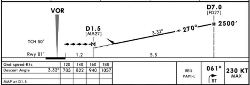
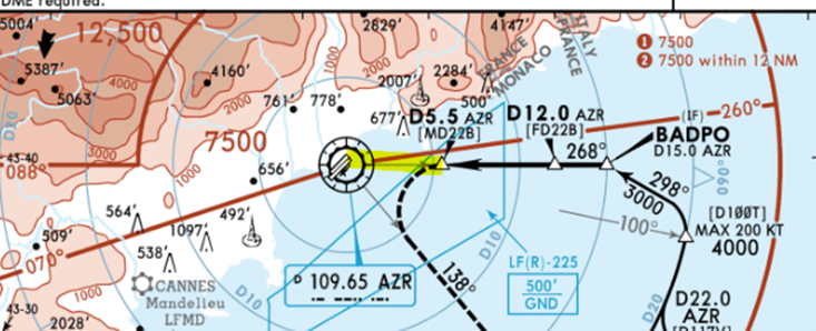
Example : Below, the required slope is 3.32° from the FAF (7 nm from the VOR) to the MAP (1.5 nm).
The table below provides a correspondence of the descent rate to follow (V/S) based on the ground speed (GS).
- Displaced threshold: It is not uncommon for the QDM not to be necessarily aligned with the runway's QFU.
Example : At Nice LFMN, the LOC is offset from the threshold of runway 04R.
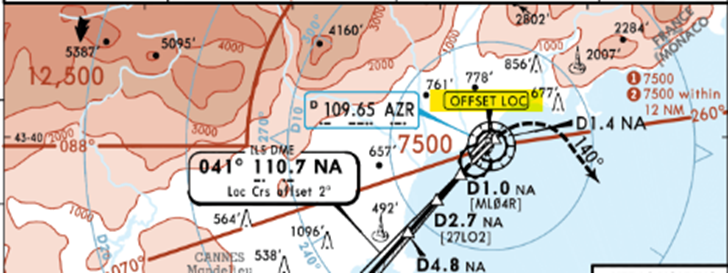
The QFU of the VOR approach is 268° for runway 22L.
- Altimeter: It is essential in all cases to display the correct QRH, especially for a non-precision approach, as the reference for descending on the final approach path is the altitude..
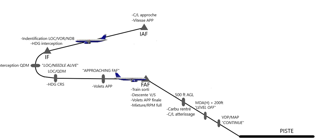
5.2.2.2 Execution
-When passing IAF :
- Perform approach checklist.
- Reduce speed to 120 kts.
-When passing IF / interception heading towards the QDM:
- Check reception of the VOR/NDB/LOC and confirm the identification.
- Set heading selector to the intercept heading.
-When LOC needle is active:
- Announce "Localizer Alive".
- Turn to intercept the LOC.
OR
-When VOR needle is at the halfway mark of the scale :
- Announce "Needle Alive".
- Turn to intercept the QDM.
OR
-Quand l’aiguille de l’ADF est à 5° :
- Annoncer « Approaching QDM ».
- Turn to intercept the QDM.
-When established on the QDM :
- Set heading selector on the ILS track (CRS).
-At 1 nm du FAF :
- Announce "Approaching FAF"».
- Reduce speed for Flaps 1 (depending on the type of aircraft).
-On the approach path :
- Extend landing gear (if applicable).
- Descend on the approach path at the appropriate descent rate (V/S).
- Reduce speed for landing configuration.
- Mixture / RPM full (if applicable).
- Check the recommended altitude based on the distance.
-At 500 ft AGL :
- Carbu heating OFF (if applicable).
- Perform landing checklist.
-At 200 ft above the MDA(H) :
- Announce "Level Off".
- Fly level until the VDP without descending below the MDA(H).
-At VDP/MAP :
- If the runway is in sight, announce "Continue" and visually descend to the runway (following the available PAPI).
- If the runway is not in sight, announce "Go Around, Flaps" and carry out the go-around procedure.
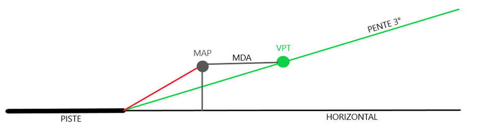
Note:
It happens on certain precision approaches that the transition from the MAP to the MDA(H) requires a steeper descent to visually reach the runway. To avoid this drawback, it is wise to calculate a visual descent point upstream of the MDA(H) in order to maintain a standard descent rate of 3° to the runway: this is the VDP (Visual Descent Point).
The VDP can then substitute for the MAP, which means that a go-around must be carried out if the runway is not in sight at the VDP. It can be determined with the following calculation :
VDP= (MDH/1000) x 3
Example :
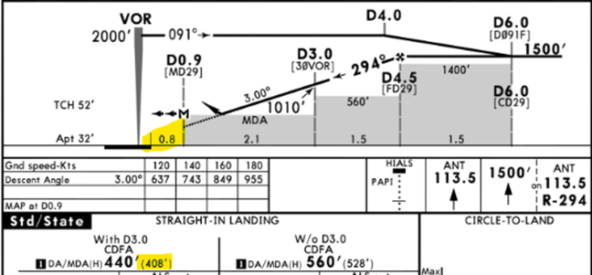
On this VOR29 approach at Antwerp (EBAW), the MAP is located 0.8 nm from the runway. The VDP would be (408 x 1000) x 3 = 1.22.
This means that the descent should begin 1.22 nm from the runway to descend on a 3° slope from the MDA of 440 ft. However, if we only rely on the 0.8 nm from the MAP, we run the risk of arriving too high on the approach and having to execute a go-around..
5.4.3.1 Circle to Land
DIn the event that there is no instrument approach available for landing on a runway but the opposite runway is equipped with one, a procedure is often established that involves making the approach, and then, at minimums, transitioning to a visual circuit to land on the runway in question.
The execution of this manoeuvre is subject to published minima.
Example :
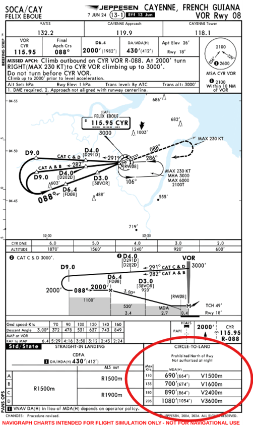
AIn the event that no approach is feasible for runway 26 at Cayenne (SOCA), it may be possible, depending on the weather conditions, to land there using the VOR approach for runway 08.
A the MDA(H) of 690 ft (Cat A), we turn right to join the downwind leg parallel to the runway, then onto the base leg to turn onto final approach and land on runway 08.
Note: It is mandatory to have visual contact with the runway once the altitude of 690 ft is reached (664 ft above ground level) and to have a visibility of 1500 m. Otherwise, it will be necessary to go around and carry out the go-around procedure. Furthermore, it is prohibited to conduct the circuit to the north of the airfield, which means that the circuit will be left-hand.
5.4.3.2 Visual Approach / Circle to land
A flight can also conclude with a visual approach for various reasons :
- No Navigation aids available.
- Shorten the flight time by flying directly to the runway.
- At the request of the ATC.
Once cleared, you simply need to join the circuit visually by following the ATC instructions (direct final approach, downwind, etc.) and proceed as you would in visual flight (VFR).
Note:
As in the case of the circle to land, the visual approach clearance does not cancel the IFR flight plan but allows for the approach to the runway once visual contact with it has been established.